![]()
Chapter 1
Antenna Basics
Luigi Boccia1 and Olav Breinbjerg2
1 University of Calabria Italy
2 Technical University of Denmark Denmark
1.1 Introduction
Antennas radiate and receive electromagnetic waves by converting guided waves supported by a guiding structure into radiating waves propagating in free space and vice versa. This function has to be accomplished by fulfilling specific requirements which affect the antenna design in different ways. In general, a number of antennas are installed in a satellite and their requirements vary depending on the application and on the mission. They can be roughly classified into three types: antennas for telemetry, tracking and control (TT&C), high-capacity antennas, and antennas for space instruments or for other specific applications. Several examples of the latter class are reported in the third section of this book.
This chapter provides an overview of the basic antenna parameters and antenna types, and it presents other basic concepts related to the space environment which will introduce the reader to the development of antennas for space applications. Although many basic definitions are presented, the chapter is not intended to provide a comprehensive background to antennas. For this reason, the reader should refer to the extensive literature available on the subject, some of which we list as references.
The chapter is organized as follows. In the first part, the main antenna parameters will be given in accordance with the IEEE Standard Definition of Terms for Antennas [1] and with the IEEE Standard Test Procedures for Antennas [2] which will be adopted throughout the book. In the second part of the chapter, basic antenna types commonly employed in spaceborne applications will be presented. In the third part of the chapter, antenna development will be related to the space environment by introducing fundamental concepts such as multipaction and outgassing.
1.2 Antenna Performance Parameters
Numerous parameters exist for characterizing the performance of antennas and in the following subsections the most significant of these are reviewed. The relevance of these antenna parameters will be seen in Chapter 3 where they are combined into the Friis transmission formula which links the available power of the transmitter to the received power of the receiver in a radio communication system.
1.2.1 Reflection Coefficient and Voltage Standing Wave Ratio
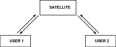
For a multi-port antenna as shown in
Figure 1.1, the scattering parameters,
, relate the equivalent voltage of the outgoing wave at port
i,
, to the equivalent voltage of the incoming wave at port
j,
, that is,
[3]. The reflection coefficient at the
i′ port is
For a single-port antenna, or for a multi-port antenna with all other ports matched (thus
for
), the reflection coefficient
equals the scattering coefficient
and, if the antenna is passive, the magnitude of the reflection coefficient is then less than or equal to 1. Note that the reflection coefficient is defined in terms of equivalent voltage which requires the existence of a well-defined mode in the port of the antenna. Furthermore, the voltage is defined at a specific position – the reference plane – in the antenna port, and the reflection coefficient is thus referenced to that position.
The voltage standing wave ratio (VSWR) is the ratio of the maximum and minimum voltages on the transmission line connected to the antenna, and it follows directly from the reflection coefficient Γ as
The scattering parameters are the main representation of antenna behavior with respect to the circuit to which the antenna is connected. This is particularly true for passive antennas while more complex parameters are required for active antennas.
1.2.2 Antenna Impedance
The input impedance of an antenna ZA is the ratio of the voltage V and current I at the port of the antenna when the antenna is isolated in free space; that is, without the presence of other antennas or scattering structures. Thus, this is sometimes referred to as the isolated input impedance. Since voltage and current are not practical quantities at radio frequencies (RFs), the input impedance is usually determined from the reflection coefficient Γ and the characteristic impedance ZC of the transmission line connected to the port of the antenna; that is,
For a linear multi-port antenna the voltage at the ith port can be related to the currents at all ports as
where Zii is the self-impedance of the ith port and Zij is the mutual impedance between the ith and jth ports. The input impedance of the ith port is then
which is seen to depend on the excitations (currents) of the other ports and therefore differs from the isolated input impedance. Thus, the input impedance of a port in a multi-port system is sometimes referred to as the active input impedance. Even the self-impedance, which is seen from above to equal the active input impedance when all other ports are open-circuited (zero current), is generally different from the isolated input impedance since the open-circuited ports may still act as scattering structures. For an antenna array, see Section 1.4, with identical antenna elements and thus identical isolated input impedances, the active input impedances may differ due to the mutual coupling. Furthermore, if the excitation of the ports is changed, for example, to scan the main beam in a phased array, the active input impedance of an individual port can vary drastically and become very poorly matched to the transmission line characteristic impedance.
If the scattering parameters are arranged in a scattering matrix
and the self- and mutual impedances in an impedance matrix
, the relationship between these, for a multi-port antenna with the common characteristic impedance of the transmission lines on the ports
ZC, can be expressed as (
is the unit matrix)
1.2.3 Radiation Pattern and Coverage
The radiation pattern is a ‘mathematical function or graphical representation of the radiation properties of the antenna as a function of space coordinates’ [1]. In the most common case, antenna radiation patterns are determined in the far-field region [4]. This region is ‘where the angular field distribution is essentially independent of the distance from a specified point in the antenna region’ [1]. Typically, the far-field region is identified by those distanc...