![]()
Chapter 1
Synchrotron Radiation: Instrumentation in Condensed Matter 1
1.1. Introduction
Since the appearance of third-generation sources, the use of synchrotron radiation has seen a significant growth over a wide range of disciplines (biology, chemistry, physics, environmental science, earth science, cultural studies, etc.). The reasons behind this success are the qualities of the beams that can be obtained (flux, brilliance, stability, etc.) and the development of optics that are able to exploit these qualities to their full potential. To this we can add the possibility of setting up a sophisticated environment around the sample, enabling it to be monitored in situ.
In this chapter we intend to describe the various types of source available in a synchrotron radiation facility and define their brilliance. We will see how the optics can be adapted to particular types of experiments (generally X-ray absorption and diffraction) in order to best preserve this brilliance. We will illustrate this by describing some of the beam lines from the SOLEIL synchrotron. We will also give examples of the sample environments installed on these beam lines (we will limit ourselves to the field of condensed matter).
1.2. Light sources in the storage ring
Synchrotron radiation is generated by emissions from charged particles (electrons and positrons) undergoing centripetal acceleration. At first this emission was considered to be a parasitic element in particle collider rings constructed for particle physics experiments. Subsequently, however, it was realized that there were a range of applications for this radiation, and the designs were optimized with the intention of improving its characteristics.
The principle behind this involves packets of electrons circulating around what is known as a storage ring at a speed close to the speed of light. The storage ring consists of a succession of curved and straight sections. The various types of light source are installed in these two types of sections.
1.2.1. Bending magnets
In the curved sections of the storage ring, electrons emit white radiation (in other words radiation consisting of a mixture of all possible energies) tangentially to their trajectory and in a narrow cone with a vertical opening angle of (
rms = 1/
), which is manifest in the time domain as a succession of sharp intensity peaks. In energy space this corresponds to continuous emission, which leads to the term “white beam”. The emission spectrum depends on the energy of the machine, the number of electrons (machine current)
and the magnetic field applied in the bending magnets. The emission spectrum in one of the SOLEIL bending magnets is shown in
Figure 1.1.
The value of
depends on the machine energy; it represents is the Lorentz factor, given by:
For SOLEIL [FIL 08], the energy of the electrons is
E=2.75 GeV, giving
= 5282 and
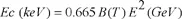
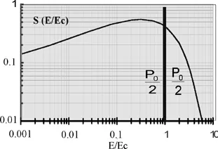
rms =0.186 mrad. The critical energy (
Ec) corresponds to the division of the curve into two parts of equal power (
P0/2). The higher the critical energy; the larger the number of high-energy photons that are available. The critical energy depends on the magnetic field of the bending magnets and the energy of the machine:
For the bending magnets of the beam lines discussed in this chapter, the critical energy is Ec = 8.6 keV.
1.2.2. Insertion devices
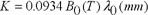
It is also possible to create photon sources in the straight sections of the ring by introducing a succession of magnetic fields with opposing polarities. These are the insertion devices that cause the electrons to deviate from their course. This causes them to oscillate about the axis of the straight section. These insertion devices are characterized by the field strength (B0) and the period (λ0) of the magnetic field. The force of the insertion is defined by the parameter K:
Two different variants exist depending on the value of K: undulators (K < 1) and wigglers (K > 1).
1.2.2.1. Wigglers
In the case of wigglers, the trajectory of the electrons oscillates with a large excursion from the axis of the straight section. The emission of light occurs in a horizontal layer of width
K/γ, corresponding to the angular excursion of the electrons. In the vertical plane the radiation is emitted into an angle of ±1/
, the same as for the bending magnets.
As viewed by an observer along the axis of the straight section, the emission is pulsed, with the time between successive emissions being the time taken for the electron to cross one period of the wiggler. This time-pulsed emission is associated with a broad-spectrum emission in energy terms. Thus, in the same way as with the bending magnets, we obtain a white beam. The different pulses of light add up in an incoherent manner, and the total flux is therefore proportional to the number of periods in the wiggler.
1.2.2.2. Undulators
In the case of undulators,
K is < 1. The trajectory of the electrons deviates only slightly from the axis of the straight section. At all points along its trajectory, the emission of light remains inside the relativistic emission cone
of the electron. For an observer on the axis of this synchrotron section, the emission is therefore continuous in time, giving an emission peaked at one particular energy. The light pulses emitted at each point along the trajectory add coherently, so that the overall flux (compared to that of an electron in a bending magnet) is multiplied by the square of the number of periods of the undulator. The magnetic field of the undulator is a function of the distance (or
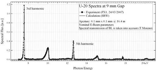
gap) between the magnetic poles of the undulator. The emission for a 9 mm gap in a U-20 type in-vacuum undulator, as used by SOLEIL, is shown in
Figure 1.2 [BRI 06].
In order to cover the full range of energies, the value of the gap is altered, modifying the magnetic field applied and altering the energy of the harmonics.
1.3. Emittance and brilliance of a source
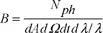
An important concept for a light source is its brilliance, which is defined by:
The brilliance is expressed as a number of photons per second, per mm2 mrad2 and for a bandwidth of 0.1%. Since we are some way from the diffraction limit, we can write:
where
x and
z are the horizontal and vertical emittances of the electron beam. In other words, they are the product of the size of the source by its divergence in each plane. High source brilliance therefore results in a low emittance. The brilliance of a bending magnet is proportional to the number of electrons. The brilliance of a wiggler is proportional to the product of the number of electrons with the number of periods in the wiggler. The brilliance of an undulator is proportional to the number of electrons multiplied by the square of the number of periods. Undulator sources are therefore by far the most brilliant sources. Conversely though, in an intermediate energy ring like SOLEIL (2.75 GeV), their critical energies are smaller than those obtained with a wiggler, where a more intense magnetic field is used (> 2
T).
The brilliance is a cons...