This comprehensive and self-contained, one-stop source discusses phase-field methodology in a fundamental way, explaining advanced numerical techniques for solving phase-field and related continuum-field models. It also presents numerical techniques used to simulate various phenomena in a detailed, step-by-step way, such that readers can carry out their own code developments. Features many examples of how the methods explained can be used in materials science and engineering applications.
Trusted by 375,005 students
Access to over 1.5 million titles for a fair monthly price.
The properties of most engineered materials have a connection with their underlying microstructure. For example, the crystal structure and impurity content of silicon will determine its band structure and its subsequent quality of performance in modern electronics. Most large-scale civil engineering applications demand high-strength steels containing a mix of refined crystal grains and a dispersion of hard and soft phases throughout their microstructure. For aerospace and automotive applications, where weight to strength ratios are a paramount issue, lighter alloys are strengthened by precipitating second-phase particles within the original grain structure. The combination of grain boundaries, precipitated particles, and the combination of soft and hard regions allow metals to be very hard and still have room for ductile deformation. It is notable that the lengthening of span bridges in the world can be directly linked to the development of pearlitic steels. In general, the technological advance of societies has often been linked to their ability to exploit and engineer new materials and their properties.
In most of the above examples, as well as a plethora of untold others, micro-structures are developed during the process of solidification, solid-state precipitation, and thermomechanical processing. All these processes are governed by the fundamental physics of free boundary dynamics and nonequilibrium phase transformation kinetics. For example, in solidification and recrystallization – both of which serve as a paradigm of a first-order transformation – nucleation of crystal grains is followed by a competitive growth of these grains under the drive to reduce the overall free energy – bulk and surface – of the system, limited, however, in their kinetics by the diffusion of heat and mass. Thermodynamic driving forces can vary. For example, solidification is driven by bulk free energy minimization, surface energy and anisotropy. On the other hand, strain-induced transformation must also incorporate elastic effects. These can have profound effects on the morphologies and distribution of, for example, second-phase precipitates during heat treatment of an alloy.
The ability to model and predict materials’ properties and microstructures has greatly benefited from the recent “explosion” of new theoretical and numerical tools. Modern parallel computing now allows billions of atoms to be simulated for times on the scale of nanoseconds. On higher scales, various continuum and sharp interface methods have made it possible to quantitatively model free surface kinetics responsible for microstructure formation. Each of these methodologies, however, comes with its advantages and deficiencies.
1.2 Free Boundary Problems and Microstructure Evolution
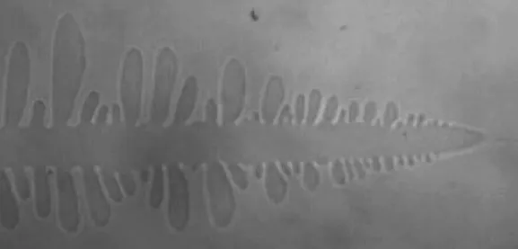
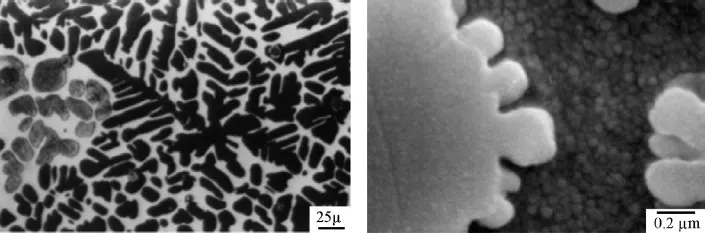
Solidification has typically served as a paradigm for many classes of nonequilibrium phase transformations that govern the formation of complex microstructure during materials processing. The most commonly recognized solidification microstructure is the tree-like dendrite pattern (which comes from the Greek word for tree, “dendron”). The most popular example of a dendrite is a snowflake, which is a single crystal of ice, solidified from water that falls through the sky. Figure 1.1 shows an image of a branch of a snowflake in an organic material known as succinonitrile (SCN) solidifying from its melt. This material is a favorite with researchers because it solidifies at room temperature and is transparent, affording us a good look at the solidification process. It is also often referred to as a “metal analogue” as it solidifies into a cubic crystal structure. Surprisingly, the properties learned from this organic material essentially remain unchanged qualitatively in metals and their alloys. Patterns like the one in Figure 1.1 are not limited to solidification. They are also found in solid-state transformations. Figure 1.2 shows dendrite patterns that emerge when one solid phase emerges from and grows within another. Microstructure modeling involves understanding the physics governing such microstructure formation.
Figure 1.1 A snowflake of succinonitrile, an organic compound that solidified at room temperature. The image shows the characteristic “dendritic” tree-like pattern of the crystal, typical of crystal formation in nearly all anisotropic solids. It is a ubiquitous shape that depends on the physics of reaction–diffusion and the properties of the surface energy between the solid and the liquid. Vincent Proton, McMaster University, 2008.
Figure 1.2Left: Solid-state dendrites in an alloy of copper (Cu) and zinc (Zn). Right: Dendrite in a nickel-based superalloy, a material commonly used in aerospace because of its very high strength. Reprinted from Refs [1] (left) and [2] (right).
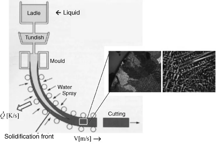
Solidification is at the heart of all metal casting technologies. Figure 1.3 shows a typical layout for casting slabs of steel used in many industries. The basic idea is that a liquid metal alloy enters a region like the one between the rollers in the figure. There the liquid is sprayed with water, which establishes a cooling mechanism that extracts heat from the casting at some rate (
). The liquid solidifies from the outer surface inward. The rate at which heat is extracted – that is, the cooling rate – is key to establishing the morphology and scale of the solidification microstructure, as seen in the inset of Figure 1.3. Typical dendrite microstructures in many steel alloys resemble those shown in Figure 1.4. In this situation, the competitive growth and interaction of a very large number of dendrites means that only partial traces of the traditional snowflake pattern survive. In fact, depending on the direction of heat extraction, cooling rate, and geometry of the cast, it is typical that only single “arms” of the characteristic snowflake pattern survive and grow. These form the branch-like striations in the figure.
Figure 1.3 Typical industrial layout for thin slab casting. Liquid is entered from top, is cooled by splashing water, and is directed – as it solidifies – at some speed (V) to the right. Most steels will then be cut and thermomechanically treated to improve their strength properties. In spite of the postsolidification treatment that the metal may receive, the so-called “as-cast” structure (inset) that is established initially is always, to some extent, present in the final product.
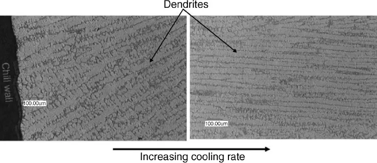
Figure 1.4 Dendrite arrays in a steel alloy. Growth is from bottom left to top right in the left figure and from left to right in the right figure. The figure on the right has been cooled much more rapidly than that on the left. The main striations are known as primary dendrites. The budding branch-like structures coming off the primary dendrites are known as secondary arms or side branches.
The kinetics of microstructure formation is traditionally modeled by a set of mathematical relations that describe the release and diffusion of heat, the transport of impurities, and the complex boundary conditions that govern the thermodynamics at the interface. These mathematical relations in theory contain the physics that gives rise to the complex structure shown in the above figures. As a concrete example, in the solidification of a pure material the advance of the solidification front is limited by the diffusion of latent heat away from the solid–liquid interface, and the ability of the interface to maintain two specific boundary conditions; flux of heat toward one side of the interface is balanced by an equivalent flux away from the other side, and the temperature at the interface undergoes a curvature correction known as the Gibbs–Thomson condition. These conditions are mathematically expressed in the following sharp interface model, commonly known as the Stefan problem:
(1.1)
where T ≡ T(
, t) denotes temperature, k thermal conductivity (which assumes values ks and kL in the solid and liquid, respectively),
the density of the solid and liquid, cp the specific heat at constant pressure, α the thermal diffusion coefficient, Lf the latent heat of fusion for solidification, γ the solid–liquid surface energy, TM the melting temperature, κ the local solid–liquid interface curvature, Vn the local normal velocity of the interface, and m the local atomic interface mobility. Finally, the subscript “int” refers to interface and the superscripts “s” and “L” refer to evaluation at the interface on the solid and liquid side, respectively.
Like solidification, there are other diffusion-limited phase transformations whose interface properties can, on large enough length scales, be described by specific sharp interface kinetics. Most of them can be described by sharp interface equations analogous to those in Equation 1.1. Such models – often referred to as sharp interface models – operate on scales much larger than the solid–liquid interface width, itself of atomic dimensions. As a result, they incorporate all information from the atomic scale through effective constants such as the capillary length, which depend on surface energy, the kinetic attachment coefficient, and thermal impurity diffusion coefficient.
1.3 Continuum versus Sharp Interface Descriptions
A limitation encountered in modeling free boundary problems is that the appropriate sharp interface model is often not known for many classes of phenomena. For example, the sharp interface model for phase separation or particle coarsening, while easy to formulate nominally, is unknown for the case when mobile dislocations and their effect of domain coarsening are included [3]. A similar situation is encountered in the description of rapid solidification when solute trapping and drag are relevant. There are several sharp interface descriptions of this phenomenon, each differing in the way they treat the phenomenological drag parameters and trapping coefficients and lateral diffusion along the interface.
Another drawback associated with sharp interface models is that their numerical simulation also turns out to be extremely difficult. The most challenging aspect is the complex interactions between topologically complex interfaces that undergo merging and pinch-off during the course of a phase transformation. Such situations are often addressed by applying somewhat arbitrary criteria for describing when interface merging or pinch-off occurs and by manually adjusting the interface topology. It is worth noting that numerical codes for sharp interface models are very lengthy and complex, particularly in 3D.
A relatively new modeling paradigm in materials science and engineering is the so-called phase field method. The technique has found increasing use by the materials community because of its fundamental origins and because it avoids some of the problems associated with sharp interface models. The phase field method introduces, along with the usual temperature field, an additional continuum field called the phase field or order parameter. This field assumes constant values in the bulk of each phase, continuously interpolating between its bulk values across a thin boundary layer, which is used to describe the interface between phases. From the...
Table of contents
Cover
Title
Copyright
Preface
1: Introduction
2: Mean Field Theory of Phase Transformations
3: Spatial Variations and Interfaces
4: Nonequilibrium Dynamics
5: Introduction to Phase Field Modeling: Solidification of Pure Materials
6: Phase Field Modeling of Solidification in Binary Alloys
7: Multiple Phase Fields and Order Parameters
8: Phase Field Crystal Modeling of Pure Materials
9: Phase Field Crystal Modeling of Binary Alloys
Appendices
Index
Frequently asked questions
Yes, you can cancel anytime from the Subscription tab in your account settings on the Perlego website. Your subscription will stay active until the end of your current billing period. Learn how to cancel your subscription
No, books cannot be downloaded as external files, such as PDFs, for use outside of Perlego. However, you can download books within the Perlego app for offline reading on mobile or tablet. Learn how to download books offline
Perlego offers two plans: Essential and Complete
Essential is ideal for learners and professionals who enjoy exploring a wide range of subjects. Access the Essential Library with 800,000+ trusted titles and best-sellers across business, personal growth, and the humanities. Includes unlimited reading time and Standard Read Aloud voice.
Complete: Perfect for advanced learners and researchers needing full, unrestricted access. Unlock 1.5M+ books across hundreds of subjects, including academic and specialized titles. The Complete Plan also includes advanced features like Premium Read Aloud and Research Assistant.
Both plans are available with monthly, semester, or annual billing cycles.
We are an online textbook subscription service, where you can get access to an entire online library for less than the price of a single book per month. With over 1.5 million books across 990+ topics, we’ve got you covered! Learn about our mission
Look out for the read-aloud symbol on your next book to see if you can listen to it. The read-aloud tool reads text aloud for you, highlighting the text as it is being read. You can pause it, speed it up and slow it down. Learn more about Read Aloud
Yes! You can use the Perlego app on both iOS and Android devices to read anytime, anywhere — even offline. Perfect for commutes or when you’re on the go. Please note we cannot support devices running on iOS 13 and Android 7 or earlier. Learn more about using the app
Yes, you can access Phase-Field Methods in Materials Science and Engineering by Nikolas Provatas,Ken Elder in PDF and/or ePUB format, as well as other popular books in Computer Science & Programming Algorithms. We have over 1.5 million books available in our catalogue for you to explore.