![]()
Chapter 1
Introduction
The modern gas turbine engine used for aircraft propulsion is a complex machine comprising many systems and subsystems that are required to operate together as a complex integrated entity. The complexity of the gas turbine propulsion engine has evolved over a period of more than 70 years. Today, these machines can be seen in a wide range of applications from small auxiliary power units (APUs) delivering shaft power to sophisticated vectored thrust engines in modern fighter aircraft.
The military imperative of air superiority was the driving force behind the development of the gas turbine for aircraft propulsion. It had to be lighter, smaller and, above all, it had to provide thrust in a form which would allow higher aircraft speed. Since aircraft propulsion is, by definition, a reaction to a flow of air or gas created by a prime mover, the idea of using a gas turbine to create a hot jet was first suggested by Sir Frank Whittle in 1929. He applied for and obtained a patent on the idea in 1930. He attracted commercial interests in the idea in 1935 and set up Power Jets Ltd. to develop a demonstrator engine which first ran in 1937. By 1939, the British Air Ministry became interested enough to support a flight demonstration. They contracted Power Jets Ltd. for the engine and the Gloucester Aircraft Co. to build an experimental aircraft. Its first flight took place on 15 May 1941. This historic event ushered in the jet age.
1.1 Gas Turbine Concepts
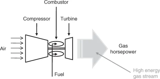
Operation of the gas turbine engine is illustrated by the basic concept shown schematically in Figure 1.1. This compressor-turbine ‘bootstrap’ arrangement becomes self-sustaining above a certain rotational speed. As additional fuel is added speed increases and excess ‘gas horsepower’ is generated. The gas horsepower delivered by a gas generator can be used in various engine design arrangements for the production of thrust or shaft power, as will be covered in the ensuing discussion.
In its simplest form, the high-energy gases exit through a jet pipe and nozzle as in a pure turbojet engine (the Whittle concept). This produces a very high velocity jet which, while compact, results in relatively low propulsion efficiency. Such an arrangement is suitable for high-speed military airplanes which need a small frontal area to minimize drag.
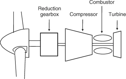
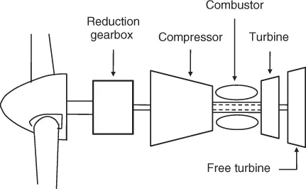
The next most obvious arrangement, especially as seen from a historical perspective, is the single-shaft turbine engine driving a propeller directly (see the schematic in Figure 1.2). As indicated by the figure the turbine converts all of the available energy into shaft power, some of which is consumed by the compressor; the remainder is used to drive the propeller. This arrangement requires a reduction gearbox in order to obtain optimum propeller speed. Furthermore, the desirability of a traction propeller favors the arrangement whereby the gearbox is attached to the engine in front of the compressor.
The Rolls-Royce Dart is an early and very successful example of this configuration. This engine comprises a two-stage centrifugal compressor with a modest pressure ratio of about 6:1 and a two-stage turbine. The propeller drive is through the front of the engine via an in-line epicyclic reduction gearbox. The Dart entered service in 1953 delivering 1800 shaft horsepower (SHP). Later versions of the engine were capable of up to 3000 SHP and the engine remained in production until 1986.
Today, single-shaft gas turbines are mostly confined to low power (less than 1000 SHP) propulsion engines and APUs where simplicity and low cost are major design drivers. There are some notable exceptions, however, one of which is the Garrett (previously Allied Signal and now Honeywell) TPE331 Turboprop which has been up-rated to more than 1600 SHP and continues to win important new programs, particularly in the growing unmanned air vehicle (UAV) market.
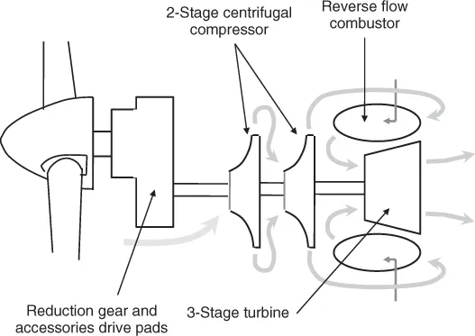
This engine is similar in concept to the Dart engine mentioned above, as illustrated by the schematic of Figure 1.3. The significant differences are the reverse-flow combustor which reduces the length of the engine and the reduction gear configuration which uses a spur-gear and lay-shaft arrangement that moves the propeller centerline above that of the turbine machinery, thus supporting a low air inlet.
A more common alternative to the direct-drive or single-shaft arrangement described above uses a separate power turbine to absorb the available gas horsepower from the gas generator.
Since the power turbine is now mechanically decoupled from the gas generator shaft, it is often referred to as a ‘free turbine’.
For the purposes of driving a propeller, this configuration (as shown in Figure 1.4) indicates a requirement for a long slender shaft driving through a hollow gas turbine shaft to the front-mounted gearbox. Such a configuration carries with it the problems of shaft stability, both lateral and torsional, together with more complex bearing arrangements.
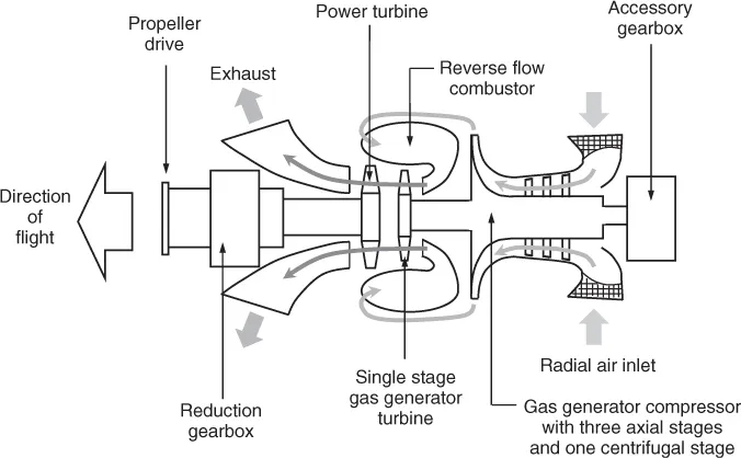
In their turboprop concept, Pratt & Whitney Canada chose to ‘fly the engine backwards’ by arranging for sophisticated ducting for the inlet and exhaust while benefitting from the stiffness and robustness of a very short drive shaft through a reduction gearbox. Their engine, the PT-6 in its many configurations, is one of the most reliable aircraft gas turbines ever built. It has an exceedingly low in-flight incident rate and has sold over 40 000 copies. It was first introduced in 1964 and is still very much in production. A conceptual drawing of the PT-6 engine is shown in Figure 1.5.
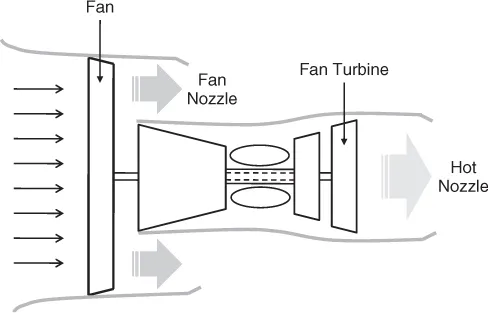
The pure turbojet produces a high-velocity jet, which offers poor propulsion efficiency with the singular advantage of higher aircraft speed, and the turboprop produces good propulsive efficiency but only at a relatively low top aircraft speed. The two configurations can however be combined to produce the turbofan engine, depicted in Figure 1.6. As is indicated in this figure, the front-mounted fan is driven by a shaft connected through the core of the engine to the second or low-pressure turbine which can be likened to the free turbine of the turboprop application. Some of the fan flow pressurizes the compressor while the remainder is expelled through a so-called ‘cold nozzle’ delivering thrust directly. Such an arrangement can produce high thrust and good propulsive efficiency, and this engine concept is one of the most common types in commercial service today.
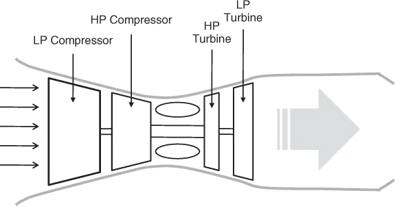
Another important configuration used in aircraft propulsion is the twin-spool turbojet engine which is essentially a twin-spool gas generator with a jet pipe and exhaust nozzle. If a second turbine can drive a large fan, it can also drive a multistage compressor with an output which is entirely swallowed by the downstream compressor. This configuration is shown in Figure 1.7.
So far in this discussion, we have assumed that the thermodynamic processes of compression and expansion are ideal and that there is no apparent limit to the magnitude of the pressure that can be obtained. In addition, we have not considered how the heat is going to be delivered to the gas to raise its temperature.
The practical implementation of the gas turbine involves turbomachinery of finite efficiency and an internal combustion process that adds heat through the burning of a hydrocarbon fuel in a combustion chamber which must be small and compact.
Throughout its development, there have been enduring themes which place specific technologies in the vanguard of engine development. The first of these themes is engine performance: the capacity of the engine to produce thrust with sufficient thermal efficiency to provide an airplane with an acceptable range while carrying a useful payload. The response to this requirement is found in the techniques of internal aerodynamics and combustion.
Saravanamuttoo et al. [1] provide a comprehensive treatment of gas turbine performance. Simple cycle calculations highlight the need for high overall engine pressure ratios and high turbine temperatures for good efficiency to be achieved. Similarly, high specific thrust demands high isentropic efficiency of each major component. Finally, size matters. In order to achieve high levels of thrust, high air flow rates must be obtained. This argues powerfully for large axial flow turbomachinery. This is very much a pacing item, since the design of such machines is very complex and the investments in equipment and facilities required to complete the development are very large indeed.
A similar argument can be made for combustion technologies. The compressor must deliver a uniform flow of air at high pressure to a combustion chamber. Fuel must be introduced into the combustor in sufficient quantities to raise the average temperature by at least 1200 °F. Assuming that the combustion process takes place at nearly stoichiometric conditions, localized temperatures in excess of 3500 °F can be expected. Excess air is essential in the gas turbine combustor to cool the flame to acceptable levels while, at the same time, mixing the hot gas to deliver a uniform, high-temperature gas to the throat of the turbine. Finally, in the interests of weight and overall engine stiffness and robustness, the combustor must be kept as short as possible. Again, this is a technology which relies heavily on experiment which, in turn, involves large investments in equipment and facilities.
The second major theme that runs throughout the development of the jet engine is that of longer life and improved reliability. This requirement has driven a relentless quest for improved materials and design methodologies. The basic need is for turbine components capable of operating continuously at elevated temperatures. (Turbine inlet temperatures for uncooled blades can run as high as 2500 °F.) Both blades and disks must be capable of withstanding the enormous stresses imposed by rotational speeds which push the materials past the elastic limit, thereby encountering low cyclic fatigue. This must be understood well enough to ensure reasonable life as well as removal before safety concerns overtake them.
The twin themes of continuous improvements in aerothermodynamics and in materials would suggest that the gas turbine engine, while sophisticated, is actually a very simple machine. In fact, the quest for improved performance has led designers to a remarkable number of variations in engine configuratio...