![]()
1
PROPAGATION OF LIGHT IN UNGUIDED MEDIA
1.1 INTRODUCTION
Free Space Optical communication (FSO) is found in a variety of telecommunication applications. In terrestrial applications, FSO technology employs a far infrared modulated beam through the atmosphere and particularly through its troposphere. In space applications, laser beams are used to establish inter-satellite links (ISL), so that a cluster of satellites forms a network in the sky [1]; in this case, satellites comprise nodes of a network, whereby the network may consists of geostationary (GS) or of low earth orbiting satellites (LEOS).
Either type of application, through troposphere or in space, owns a different set of issues [2]. In space the distance is very long and the satellite receivers may or may not face the sun, whereas in troposphere the medium is not homogeneous or stable. A third type of application comprises a stationary FSO node communicating with a moving FSO node, with additional tracking issues. As such, engineering FSO requires interdisciplinary expertise, so that the final FSO network provides high data rate links with reliability and at the expected performance under all or most environmental conditions in a profitable manner; the laser beam and the medium it travels through are two important entities of the FSO network.
1.2 LASER BEAM CHARACTERISTICS
1.2.1 Wavelength
The laser beam that is used in FSO links has a wavelength of either 800 nm, 1310 nm, or 1550 nm. The mast popular of the three is 1550 nm for the following reasons:
- The 800 nm is generated by low cost vertical cavity surface emitting lasers (VCSEL) laser technology but the beam has low power and therefore the beam is modulated at very low data rates, up to 100 Mb/s and for link lengths of few hundred meters.
- The 1310 nm used to be a popular wavelength because of the distributed feedback (DFB) and Fabry-Perot type lasers, which support higher power than the VCSEL and therefore higher data rate and/or longer link lengths.
- The 1550 nm has been the most popular of all because it supports higher power levels, Gb/s data rate, longer link lengths, and also wavelength division multiplexing (WDM) technology [3, 4]; that is, several wavelengths in the 1520–1570 nm range and ITU-T standard compliant [5–8]; that is, an aggregate data rate which is the product of the number of different optical channels in the beam times the data rate in each channel. In some WDM applications, the 1310 nm is multiplexed with the 1550 nm to provide a two-channel WDM beam; this is acceptable in applications that do not require a large aggregate data rate; in addition, the 1310 and 1550 nm channels have large channel separation that turns out to be beneficial and convenient in receiver filter design. Moreover, a long-pass optical filter at the receiver rejects most wavelengths below the 1300 nm and it greatly reduces the solar background radiation (SBR) interference. The sun’s photosphere emits electromagnetic radiation in a wide spectrum that is centered at a wavelength of 500 nm (the visible spectrum is from 400 to 700 nm) and at an average temperature in excess of 5500°C; the sun’s radiation also includes wavelengths in the radio, Ultra Violet (UV), X-ray and Gamma-ray bands.
1.2.2 Beam Profile and Modes
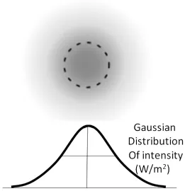
As the laser beam emerges from the device, the intensity distribution along its cross-section is not uniform but it usually has a distribution; if the distribution is Gaussian, the beam is also termed “Gaussian”.
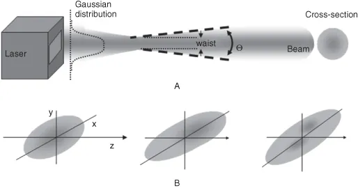
The cross-section profile of the beam is of importance; in general, it is supposed to be circular with a uniform Gaussian distribution of 360°. Typically, lasers that emit beams with a pure Gaussian distribution are operating on the fundamental transverse mode, or “TEM00 mode”, Figure 1.1.
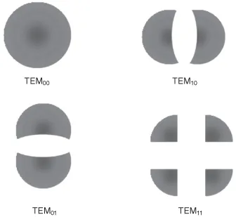
In general, the analysis of beam profile is complex and the Hermite-Gaussian equations are used to describe the beam modes, which are designated as “TEMmn”, where m and n are polynomial indices in the x and y directions. With pure Gaussian distribution, m = n = 0 and thus TEM00. Some lasers, however, are not as uniform and they operate in different modes, Figure 1.2.
1.2.3 Beam Divergence
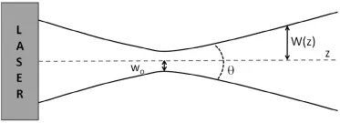
Besides the non-uniformity of the beam cross section, the beam is not purely parallel in the z-direction (the direction of propagation). Even if the beam emerges parallel, it does not remain so because of spatial diffraction, which causes the beam to first narrow at a point known as “waist”, w0, and then diverge at an angle Θ, Figure 1.3.
A laser beam propagating in the z direction and with Gaussian distribution across the beam is mathematically described by:
where E is the amplitude of the electric field, w
o is the minimum beam waist where the phase is constant, w(z) is the beam waist at distance z, r is the radius of the waist at z, k is the wave number approximated to (k ∼ 2π / λ), R(z) is the radius of the wave curvature at distance z, and z
o is the Rayleigh distance where the beam has expanded to
.
Beam divergence expands the diameter of the beam cross-section over distance, known as geometrical spreading, which reduces rapidly the optical power density of the beam, known as geometrical spreading loss. Starting with a cross section of one or less millimeter diameter at the aperture of the laser device, as a result of geometrical spreading the laser beam will be few meters in diameter after few kilometers. Beams with negligible divergence, or with an almost constant radius over the axis of propagation z are known as collimated beams; an optical device known as collimator helps to accomplish this.
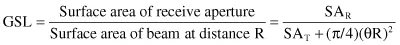
The geometrical spreading loss (GSL) for typical laser beams with surface area of the transmit aperture SAT, at distance R where the receiver is with surface area of the receive aperture SAR, with constant divergence angle θ, and assuming constant power distribution across the beam, is estimated at:
Typical values for SAT and SAR are in the range 0.004–0.025 m2, for an angle θ of 1 to 3 mrad.
The aforementioned spreading loss is for an ideal beam and also a good approximation. However, practical beams do not have a constant power distribution across the beam but they may have a Gaussian distribution; as aforementioned, laser beams are not purely conic but they may have a longitudinal profile with a waist of radius W0, after which they diverge at an almost constant angle. In calculations, one may use the full width at half-maximum (FWHM), which is provided in the manufacturer’s data sheets; the FWHM, or 50% of intensity, is 0.59W0.
Additionally, in practical beams the cross-section and the intensity distribution may be neither circular nor Gaussian, Figure 1.4; non-circular cross-section reduces the coupling efficiency of the beam onto the fiber and onto the FSO receiver due to irregular power distribution and irregular divergence. For non-Gaussian profiles, an integral formula may be used for waist and radius calculations.
The optimum waist, w0,optimum, for a wavelength λ at a distance z from the source...