![]()
Chapter 1
Introduction
A fundamental design concern for system designers of wireless communication systems is modeling distortion introduced by the nonlinear behavior of the devices incorporated in the design. Nonlinearity in wireless communication systems usually exists in the RF front ends and is produced by nonlinear devices such as power amplifiers, low-noise amplifiers, mixers, etc. Nonlinearity is responsible for introducing signal components that contribute to degrading system performance in a similar fashion to system noise, interference or channel impairments.
In order to understand the effects of nonlinear distortion on the performance of wireless communication systems, it is important to understand the architecture of these systems and the components that are responsible for introducing nonlinear distortion. On the other hand, it is also important to understand how these systems can be modeled and simulated. Modeling and simulation of nonlinear systems is an important step towards the efficient design of modern communication systems.
In this chapter, an overview of nonlinearity and nonlinear distortion in wireless systems is given. The common sources of nonlinearity in wireless communication system are presented. Then, the concept of nonlinear distortion produced by the nonlinear behavior and its relationship to the performance of wireless systems is given in the subsequent sections. In the last section of this chapter, an overview of the most common modeling and simulations approaches of nonlinear systems and circuits are presented that will serve as an introduction to subsequent chapters that discuss modeling and simulation of nonlinear distortion.
1.1 Nonlinearity in Wireless Communication Systems
Nonlinearity in wireless systems is originated in the nonlinear devices incorporate in the design of the transmitter and the receiver. The main blocks that introduces nonlinear distortion are mixers, power amplifiers in wireless transmitters and low-noise amplifiers in wireless receivers.
1.1.1 Power Amplifiers
Power Amplifiers (PAs) are devices that are used at the end of the transmitter chain in order to produce a signal with a power suitable for transmission through an antenna. In a wireless transmitter, a baseband signal sent to a PA that is connected to an antenna through a matching circuit after being modulated and up-converted. The PA performs power amplification by multiplying the signal by a gain factor that results in an amplified signal whose power is much higher than the input signal. Ideally, a PA has constant gain across all input powers, however, a practical PA has a maximum output power that is determined by the DC input power. Hence, as this limit is approached gradually, the apparent gain of the PA decreases with increasing the input power.
Therefore, depending on the input operating power, the PA is considered linear if it is operated in a power range within the linear amplification range of its characteristics. If the amplifier is operated close to or within the saturation region of its characteristics, then it is considered nonlinear. It is usually desirable to operate the PA near its saturation region in order to obtain maximum power efficiency; however, this means that nonlinear distortion is introduced at the output of the PA, which is undesirable specially when the input signal has a varying amplitude.
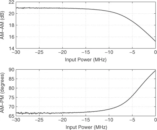
PAs are characterized by their gain versus input power curves for single-tone input that are known as Amplitude Modulation–Amplitude Modulation (AM–AM) conversion characteristics. In a typical AM–AM characteristics, the gain of the PA remains constant (output power increases linearly) with increasing input power up to a saturation point where the gain drops (output power remains constant with increasing input power). This is due to the input/output characteristics of the active device (transistor) incorporated in the PA design. Saturation of the PA characteristics is a manifestation of the PA nonlinearity where the output power does not follow the input power by a constant gain. Another manifestation of nonlinearity is the phase characteristics of the PA where the phase of the output signal deviates from the input phase by an angle that depends on the input signal power. These phase characteristics are called the Amplitude Modulation–Phase Modulation (AM–PM) characteristics and they measure the phase distortion introduced by a PA. AM–PM characteristics are mainly due to voltage dependent collector capacitance (caused by a varying depletion layer width) (Cylan, 2005).
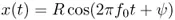
The AM–AM and AM–PM characteristics can be formulated by considering a single tone signal of the form
where R is the signal amplitude, f0 is the tone frequency and ψ is its phase. The output of nonlinearity can be expressed as
where F[.] is the amplitude distortion as a function of the input amplitude and represent the AM–AM characteristics of the nonlinear device and Φ[.] is the phase distortion as a function of the input amplitude and represents the AM–PM characteristics. Figure 1.1 shows a typical AM–AM and AM–PM characteristics of a PA.
1.1.1.1 Memory Effects
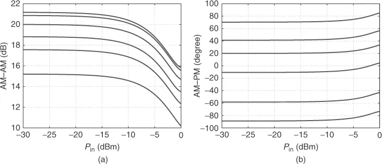
The AM–AM and AM–PM characteristics define the PA linearity at a single frequency. However, the PA characteristics may differ at different frequencies. This is due to the memory effects of the PA that are usually caused by the time constants in the biasing circuit or are due to the impedance mismatch with the amplifier. Figure 1.2 shows the AM–AM and AM–PM of a PA at different frequencies. In fact, the existence of the AM–PM characteristics indicates that the PA has memory since a memoryless PA has only AM–AM characteristics. However, if the time constants of the memory are smaller than the maximum signal envelope frequency, the system is called a quasi-memoryless system. In general, if the bandwidth of the PA is much larger than the modulation bandwidth of the signal, the PA can be considered as memoryless. Memory effects can manifest themselves as hysteresis in the time domain, which causes the intermodulation products of a two-tone test to be asymmetrical in the frequency domain.
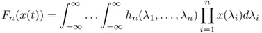
The most common approaches to modeling the wideband behavior (i.e. memory effects) of nonlinear amplifiers are those based on Volterra series analysis. Volterra series analysis represents an analytical approach to modeling nonlinearity since it represents nonlinearity in a similar way in which Taylor series does for analytic functions. A general Volterra series model of a nonlinear system is described by the following functional expansion of continuous functions (Lunsford, 1993):
where Fn(x(t)) is the Volterra functional and is defined as
where hn(λ1, …, λn) is the n-dimensional Volterra kernel that can be symmetric without loss of generality and leads to a unique set of Volterra kernels. Other models for nonlinear systems with memory are discussed in Chapter 3.
1.1.1.2 PA Classes
PA designs fall into a number of classes according to their biasing conditions. Different classes have different nonlinear characteristics and hence, different power efficiencies. The most common PA classes are Class A, B, AB, C, D, E and F, where Class A, B and AB being linear (with low power efficiency) whereas the others are nonlinear (with high power efficiency). The PA class is distinguished by its biasing conditions that are chosen to give a desired PA linearity at the expense of its efficiency (Briffa, 1996; Cripps, 2000).
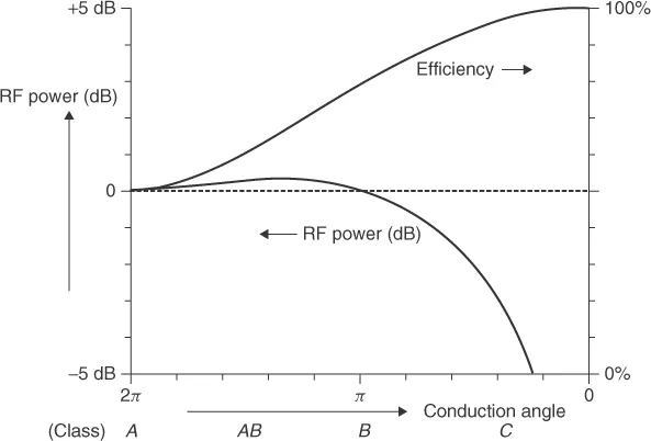
Higher positive bias voltages provide a higher linear region of operation. However, positive bias voltages (such as class A operations) lead to higher conduction angles, which means low power efficiency. On the other hand, negative bias voltages (such as with class C operation) lead to lower conduction angles but this requires a higher input drive level to maintain power efficiency. This makes the PA operate near saturation, which means nonlinear operation. Figure 1.3 shows typical RF output power and power efficiency of a PA versus conduction angle where different classes are defined (Cripps, 2000).
1.1.2 Low-Noise Amplifiers (LNAs)
The low-noise amplifier is the first block in any RF receiver and is responsible for the amplification of the received signal, which usually has very low power. An LNA in an RF receiver, therefore, plays an important role in the quality of the reception process, and hence the design of LNAs represents a limiting factor in the performance of the overall communication system.
Since an LNA in an RF wireless receiver is required to amplify weak signals in the presence of noise, the design of an LNA requires a tradeoff of a number of factors such as linearity, noise performance, stability, power consumption and complexity. Linearity and noise performance are responsible for determining the dynamic range of the amplifier where the minimum and maximum allowed signals levels are determined. An LNA is designed with its gain compression (due to nonlinearity) determined by the maximum received signal level expected in a certain application. On the other hand, an LNA is designed with a noise performance such that its added noise is below the minimum expected received signal level. Therefore, the main difference between LNAs and PAs is that in PA design noise performance is not an issue since PAs usually operate with input signal powers that are much higher than the inherent noise of the PA circuit. This means that the LNA nonlinearity is...