![]()
Part I
Mechanics and Modeling
Microelectronic devices, optoelectronic devices, and MEMS (micro-electrical-mechanical- systems) devices and their systems are mainly being manufactured with a silicon chip, or chips, in various compact package configurations to satisfy cost and performance requirements. A typical package and assembly is manufactured through many processes (both front-end and back-end), followed by many severe reliability qualification tests. A typical packaging assembly consists of components of different materials with different mechanical and thermal properties, and geometric discontinuities exist in terms of vias, comers, free edges, interfaces, surfaces, and composites. Non-uniform temperature and moisture fields during each process of packaging and assembly, testing, storage, and operation often subject these materials and components to various failure modes, for example, metal line voiding, passivation cracking, die cracking, fine metal line smearing, package swelling, warpage, and delamination. If failure occurs in a process step of manufacturing, and results in the component not being processed, yield can be a big issue, and popcorning during the reflow of plastic packaging onto the board is such an example. System functionality tests performed on these packages and assemblies, in general, will not detect the majority of these failures. This may not cause catastrophic failure but may cause performance degradation and failure before the designed life cycle. Due to the rapid advancement of the related industries, information on detailed failure initiation, growth and performance degradation is not easily available and it is a challenging task for the modeling and simulation community. Closed-form solutions are mostly unavailable due to the many nonlinearities such as material nonlinearities for many polymer and solder materials, geometrical nonlinearity such as membrane deformation in sensors, force nonlinearity such as contact and debonding, contour change for sequential process steps, micro-structural changes such as for annealing, damage development, and mass transport for electromigration and wetting, just to list a very few examples. Serious study is essential for modeling and simulation. Constitutive models for engineering materials are a must to avoid a wrong analysis which can easily result in engineers arriving at wrong conclusions or no conclusions at all. In the first part of the book, we will introduce constitutive models and leave the definition of the basic concepts such as stress, strain, and so on, to Appendix A. Then we will briefly present the finite element methods and some of the advanced features such as sub-modeling, sub-structure, and element birth and death. Material testing for small samples is presented to show the uniqueness of our samples as compared to bulk structures for traditional industries. User-supplied subroutines are also presented with solders as an example. Multi-physics and multi-scale modeling is presented by briefly introducing molecular dynamics (MD), while leaving most of MD to Part IV. Validation tools and their applications for both on-line testing and off-line quality analysis are presented. Fracture mechanics with the focus on the interfacial fracture mechanics is presented and the concurrent engineering approach is presented as a platform for leading research laboratories which are product oriented and have a strong desire to shorten the time-to-market and time-to-profit.
![]()
Chapter 1
Constitutive Models and Finite Element Method
In this chapter, the basic equations of continuum mechanics are introduced. It is assumed that the readers already have a basic prior knowledge of the subject. Therefore, lengthy derivations are omitted, such information being provided in the Appendix. Only equations that are needed later for deriving the mechanics theories are outlined. Most equations are adopted from several famous references listed in the literature of this chapter, including ABAQUS theory manual (Belytschko et al., 2000; Hibbit et al., 2008).
1.1 Constitutive Models for Typical Materials
1.1.1 Linear Elasticity
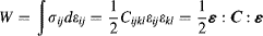
In many engineering applications involving small strains and rotations, the response of the material may be considered to be linearly elastic. The most general way to represent elastic tensor C relation between the stress and strain tensors is given by:
where Cijkl are components of the 4th-order tensor of elastic moduli. This equation is the generalized Hooke's law which incorporates a fully anisotropic material response.
The strain energy per unit volume, often called the elastic potential, W, is generalized to multiaxial states by:
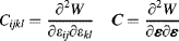
The stress is then given by:
which is the tensor equivalent of Equation (1.2). The strain energy is assumed to be positive definite:
with equality if and only if
which implies that
C is a positive-definite 4th-order tensor. From the symmetries of the stress and strain tensors, the material coefficients have the so called minor symmetries:
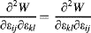
and from the existence of a strain energy potential Equation (1.2) it follows that:
If W is a smooth function of ε, Equation (1.6) implies a property called major symmetry:
since smoothness implies:
The general 4th-order tensor
Cijkl has
independent constants. These 81 constants may also be interpreted as arising from the necessity to relate nine components of the complete stress tensor to nine components of the complete strain tensor, that is, 9 × 9 = 81. The symmetries of the stress and strain tensors require only that six independent components of stress be related to six independent components of strain. The resulting minor symmetries of the elastic moduli therefore reduce the number of independent constants to 6 × 6 = 36. Major symmetry of the moduli, expressed through
Equation (1.7) reduces the number of independent elastic constants to
, for
n = 6, that is, the number of independent components of a 6 × 6 matrix.
Considerations of material symmetry further redu...