![]()
Chapter 1
Laser Rapid Manufacturing: Technology, Applications, Modeling and Future Prospects 1
This chapter deals with the various aspects of laser rapid manufacturing (LRM) and provides an insight into the underlying basic principles and applications of this revolutionizing laser based manufacturing technology. The details of the LRM system, relevant processing parameters, process modeling, control systems and future prospects of LRM are presented and discussed.
1.1. Introduction
Theodore H. Maiman, the inventor of the first working laser, described it as “a solution looking for a problem” because few appreciated its manifold potential applications [EVA 04]. However, the scenario after a journey of five decades is vivid and today lasers find applications in everyday life.
Due to unique properties, lasers have established themselves from “a solution looking for a problem” to “a solution for many problems”. The field of manufacturing has also not been left untouched. As lasers can heat, melt and vaporize any material, they are exploited in manufacturing for cutting, welding, surface hardening, cladding, alloying, peening and additive manufacturing.
In 1986, lasers stepped into the arena of additive manufacturing with the invention of stereolithography – the first additive manufacturing process by Chuck Hull [CHU 86]. In this process, a UV laser beam is scanned on the surface of a liquid UV-curable photopolymer “resin” to selectively cure and form a cross-section of an indented object. A number of cross-sections are thus formed one over another to shape the whole object. This evolved the concept of additive manufacturing into a rapid prototyping process. Soon after the invention of stereolithography, the laser was deployed in “selective laser sintering” to fuse the polymer/polymer coated metal powders to shape the prototype components [DEC 89].
The subsequent advances in the field of high power lasers, computer aided design and manufacturing (CAD/CAM), powder metallurgy and allied electronics translated the rapid prototyping into 3D metallic components for various engineering applications [KRE 95].
Moreover, the paradigm shift in global economics, from a seller’s market to a buyer’s market, challenged industries for the immediate delivery of the best quality product with all possible features at the lowest possible price in order to ensure survival [CHI 11]. This propelled research and development in the area of rapid manufacturing at various renowned universities and national laboratories. In this growing list of rapid manufacturing, laser rapid manufacturing (LRM) is one of the leading manufacturing techniques.
1.2. Laser rapid manufacturing
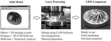
LRM is one of the advanced additive manufacturing processes that is capable of fabricating engineering components directly from a solid model. In this technique, a solid model of the component to be fabricated is made either by a 3D imaging system, a designer using computer aided design (CAD) software or by math data as an output of numerical analysis. The model obtained thus is sliced into thin layers along the vertical axis. The thin layers are converted into corresponding numerical controlled (NC) code and are sent to a LRM station in a suitable format (e.g. G&M code).
A LRM station employs a laser beam as a heat source to melt a thin layer onto the surface of the substrate/deposited material and fed material to deposit a new layer as per the shape and dimensions defined in NC code. A number of such layers deposited one over another result in 3D components directly from the solid model. Figure 1.1 presents the general scheme of the LRM technique.
LRM eliminates many manufacturing steps such as materials-machine planning, man-machine interaction, intermittent quality checks, assembly and related human errors, etc. Therefore, LRM offers many advantages over conventional subtractive techniques, such as reduced production time, better process control and the capability to form functionally graded parts. It is also an attractive candidate for refurbishing applications because of the low heat input, limited dilution with minimal distortion and capability of adding finer near-net shaped features to the components.
Manufacturing techniques, similar to LRM, are being developed with different names at various laboratories around the world. At Sandia National Laboratory, USA, laser engineered net shaping (LENSTM) is being developed with the prime focus on creating complex metal parts in a single day [SAN 10]. The National Research Council, Canada is developing freeform laser consolidation for manufacturing structural components for advanced robotic mechatronic systems [XUE 01].
Automated laser fabrication (ALFa) is being developed, at the University of Waterloo, Canada, to produce low cost tungsten carbide components [PAU 08]. Selective laser cladding (SLC) at the University of Liverpool, UK and direct metal deposition at the University of Michigan, USA are being used to deposit critical surfaces on prime components [DAV 06, HE 10]. Laser powder deposition (LPD) at the University of Manchester UK and direct metal deposition/laser additive manufacturing at Fraunhofer Institute, Germany are being augmented for the fabrication of high performance materials [MOA 09]. Researchers at Tsinghua University, China, are working on diverse area and evaluating the technology for the potential development of graded Ti alloys for aeronautical applications, nickel alloys for power plants and various in situ repair applications [ZHO 10]. Thus, the ongoing global research is spearheading towards the deployment of this novel fabrication technology for improving the quality of the products, the possibility of engineer integrated multi-materials and multi-functional components and enhancing economic or procedural benefits.
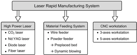
1.3. Laser rapid manufacturing system
A LRM system consists of the following three primary subsystems:
a) a high power laser system;
b) a material feeding system;
c) a computerized numerically controlled (CNC) workstation.
Figure 1.2 presents the various options used for primary LRM subsystems.
1.3.1. High power laser system
In LRM, a high power laser system is used as a heat source to melt a thin layer of substrate/previously deposited layer and fed material. CO2 laser, Nd:YAG and diode lasers are most widely used for the application. High power fiber lasers are the new entrant in this application domain [VAL 10]. For laser material processing involving metals, Nd:YAG, diode and fiber lasers have better absorption due to shorter wavelengths, but CO2 lasers are still used because of established systems and procedures. Generally, laser energy intensities of 20 kW/cm2 to 60 kW/cm2 are used for CO2 lasers, while 150 kW/cm2 to 200 kW/cm2 are used for pulsed Nd:YAG lasers [KRE 95, SUN 05].
The high energy intensity requirements for pulsed Nd:YAG lasers are attributed to re-melting and solidification of a molten pool during the processing. The basic pre-requisite for laser beam energy intensity distribution is symmetry along the laser beam’s axis of propagation. This allows uniform material deposition independent of the processing direction. Therefore, a multimode laser beam with a flat top distribution is the most widely used. Gedda et al. studied the energy distribution during a LRM process, using a CO2 laser and a Nd:YAG laser [GED 02]. The observations are summarized in Table 1.1.
Table 1.1. Redistribution of laser power during laser cladding
| Use of laser power | CO2 laser | Nd:YAG laser |
| Reflected off the cladding melt | 50% | 40% |
| Reflected off the powder cloud | 10% | 10% |
| Heat the substrate | 30% | 30% |
| Melt the substrate/previously deposited layer | 10% | 20% |
Table 1.1 clearly indicates that 10% of the laser energy is utilized to melt the substrate layer/previously deposited layer in the case of a CO2 laser, while 20% of the energy of a Nd:YAG laser is used due to increased absorption. When metals (such as SS316L) are in solid state, the laser energy utilization for Nd: YAG laser is increased by a factor of 1.3. This factor reduces as the temperature rises and is the same for both the lasers in molten/liquid states. Thus, about 769 W of the continuous wave Nd:YAG laser replaces 1 kW of the continuous wave CO2 laser with the same beam product parameter for almost the same results during LRM. Since the wave length of other commonly used lasers (diode and fibre) is close to the Nd:YAG laser, similar results compared to the CO2 laser are pertinent.
1.3.2. Material feeding system
Among material feeders, there are three main types of feeding techniques: wire feeding, pre-placed powder bed and dynamic powder blowing.
1.3.2.1 Wire feeders
...