![]()
CHAPTER 1
INTRODUCTION TO MICROWAVE LOS LINK SYSTEMS
1.1 INTRODUCTION
From a generic standpoint, a telecommunication network enables the exchange of information among users or devices that can be either fixed or mobile. This general view contains the first simple classification of telecommunication networks into fixed and mobile. Independently of the mobile or fixed nature of the target devices, the signals involved in the communication process transport digitized information that is associated with final services such as voice, pictures, video, or general data.
Every network is composed of two basic components: network nodes and transmission systems. The network nodes provide the control, access, aggregation/multiplexation, switching, signaling, and routing functions. The transmission systems enable the transport of signals either from the user devices to the network nodes or between different nodes of the network. The transmission systems can be based on different delivery media. Usually, the transmission media have been divided into wireless systems, where the information is delivered by means of electromagnetic waves that propagate through the atmosphere, and systems based on transmission lines, where the electric or optical signals propagate through a closed medium. The metallic transmission of electric signals uses lines that usually are copper pairs or coaxial cables, whereas the optical signals are sent over glass fiber cables.
Transmission systems can be found in any of the two subnetworks that compose a generic telecommunications network: access network and transit network. The access network enables the communication between the network and the user devices, whereas the transit network provides all the required functions that interconnect different access sections, including network control, signaling management, switching, interfacing with other networks, etc.
In this network context, a radio link of the fixed service (FS) [as per Radiocommunication Sector of the International Telecommunication Union (ITU-R) terminology)] is any radiocommunications link between two fixed stations based on the propagation of signals through the atmosphere at frequencies higher than 30 MHz. Currently, there is a tendency to use more the generic term of fixed wireless system (FWS), which is used to identify the telecommunication systems operated for FSs and that are used in access and transport application scenarios. Those systems are conveyed by electromagnetic wave propagation, in any form, with a limit that has been set in 3000 GHz. Terrestrial point-to-multipoint systems, terrestrial point-to-point systems, high-frequency (HF) systems, high-altitude platform systems (HAPS), and even free space optic links fall into the FWS category.
Microwave line-of-sight (LOS) links covered by this book are a subgroup of the FS or FWS general classifications. Microwave LOS links are composed of point-to-point systems between two terrestrial stations that transmit and receive signals taking advantage of the propagation of waves through the lower part of the atmosphere (troposphere). Microwave links operate in LOS condition in frequencies from 400 MHz to 95 GHz under specified availability and quality conditions. These systems are in practice referred as microwave links (MW links), LOS microwave, fixed service radio links, or simply radio links.
The frequency limits mentioned earlier are associated with the frequency band assignments that international regulatory bodies have reserved for fixed service links. Currently, a majority of the systems operate in frequency bands between 4 and 40 GHz. Higher frequency bands are used in links where the path between stations is rather short (usually less than 1 km and, in any case, no longer than a few kilometers due to availability constraints associated with rain attenuation).
A basic point-to-point microwave LOS link is composed of two nodal stations, each one at the edge of the link path, without obstacles in the propagation path that could cause blocking or diffraction, and that use antennas with high directivity, also named narrow-beam antennas.
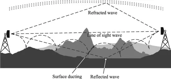
Microwave LOS links are designed to preserve the LOS propagation path as the main propagation mechanism. This condition implies that the direct component of the space wave is well above the terrain irregularities and any diffraction effects are considered negligible under standard conditions. In practice, the LOS component coexists with additional propagation modes such as the reflection on the surface of the earth, diffraction in obstacles due to anomalous refractive conditions and multipath propagation originated both on the surface of the earth and on higher layers of the troposphere. In the design process of a MW link, the availability of accurate terrain maps, which also contain any man-made construction candidate to create diffraction, is a key requirement. Figure 1.1 shows a simplified model of the possible propagation modes in a point-to-point link.
In the likely event that path distance between the locations that will be communicated exceeds the LOS distance, due to terrain irregularities or simply due to the curvature of the earth, the link will be divided into concatenated shorter sections (called “hops”) that are created by means of including repeater stations.
In most cases, microwave LOS links are bidirectional systems, with full duplex capacity provided by frequency division multiplex schemes. The simplest example would require two carriers, each one aimed at transporting the information in one direction. An assignment of two frequencies, each one for each direction of the communications, is called radio channel. Sometimes, LOS links can be simplex systems, transporting information in only one direction. An example of this application can be found in the transport section of terrestrial broadcast systems, where the video, audio, and data are conveyed from a production or aggregation center to the broadcast stations that will later broadcast the contents to the end users.
This chapter provides an overall view of the microwave LOS links, describing the specific terminology that will be used in this book, the most relevant characteristics of the technologies involved and identifying the most widespread application fields of microwave LOS links. The chapter contains the basic principles of the planning and design process of a microwave LOS link, starting from the definition of a link budget and identifying the main signal degradation sources that influence the fulfillment of the quality requirements of the link. The perturbation sources considered will be related to propagation through the troposphere, noise sources, and interferences. After the introductory picture given in this chapter, each one of the design procedures and modules will be covered in detail in later chapters.
1.2 HISTORIC EVOLUTION OF RADIO LINKS
The first experimental microwave LOS link was designed and installed by the Bell Labs in 1947. The system was intended to provide a two-way communication between two stations in New York and Boston. The link was an analog system in the 4 GHz band that used frequency modulation and frequency division multiplex techniques. The equipment was based on vacuum tubes. The evolution of this system led to further developments in the United States, Australia, Canada, France, Italy, and Japan during the 1950s. The preferred bands during this period were 4 and 6 GHz. In this context, in 1960, the National Long Haul Network was designed to connect the East and West Coasts of the United States of America, with a total length of 6500 km and about 125 active repeater stations.
In 1968, the first digital microwave LOS link was installed in Japan. This first digital system operated in the 2 GHz band, using phase shift keying (PSK) modulation with an equivalent capacity of 240 telephone channels. After this first digital landmark...