![]()
1
Multimedia Over Packet
1.1 TRANSPORTING VOICE, FAX, AND VIDEO OVER A PACKET NETWORK
1.1.1 A Darwinian view of voice transport
1.1.1.1 The circuit switched network
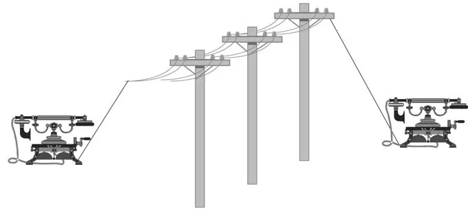
The most common telephone system on the planet today is still analog, especially at the edge of the network. Analog telephony (figure 1.1) uses the modulation of electric signals along a wire to transport voice.
Although it is a very old technology, analog transmission has many advantages: it is simple and keeps the end-to-end delay of voice transmission very low because the signal propagates along the wire almost at the speed of light.
It is also inexpensive when there are relatively few users talking at the same time and when they are not too far apart. But the most basic analogue technology requires one pair of wires per active conversation, which becomes rapidly unpractical and expensive. The first improvement to the basic ‘baseband’ analog technology involved multiplexing several conversations on the same wire, using a separate transport frequency for each signal. But even with this hack, analog telephony has many drawbacks:
- Unless you use manual switchboards, analog switches require a lot of electromechanical gear, which is expensive to buy and maintain.
- Parasitic noise adds up at all stages of the transmission because there is no way to differentiate the signal from the noise and the signal cannot be cleaned.
For all these reasons, most countries today use digital technology for their core telephone network and sometimes even at the edge (e.g., ISDN). In most cases the subscriber line remains analogue, but the analogue signal is converted to a digital data stream in the first local exchange. Usually, this signal has a bitrate of 64 kbit/s or 56 kbit/s (one sample every 125 μs).
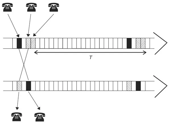
With this digital technology, many voice channels can easily be multiplexed along the same transmission line using a technology called time division multiplexing (TDM). In this technology, the digital data stream which represents a single conversation is divided into blocks (usually an octet), and blocks from several conversations are interleaved in a round robin fashion in the time slots of the transmission line, as shown in Figure 1.2.
Because of digital technology, the noise that is added in the backbone does not influence the quality of the communication because digital ‘bits’ can be recognized exactly, even in the presence of significant noise. Moreover, digital TDM makes digital switching possible. The switch just needs to copy the contents of one time slot of the incoming transmission line into another time slot in the outgoing transmission line. Therefore, this switching function can be performed by computers.
However, a small delay is now introduced by each switch, because for each conversation a time slot is only available every T μs, and in some cases it may be necessary to wait up to T μs to copy the contents of one time slot into another. Since T equals 125 μs in all digital telephony networks, this is usually negligible and the main delay factor is simply the propagation time.
1.1.1.2 Asynchronous transmission and statistical multiplexing
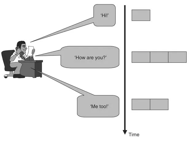
Unless you really have a point to make, or you’re a politician, you will usually speak only half of the time during a conversation. Since we all need to think a little before we reply, each party usually talks only 35% of the time during an average conversation.
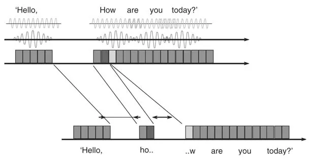
If you could press a button each time you talk, then you would send data over the phone line only when you actually say something, not when you are silent. In fact, most of the techniques used to transform your voice into data (known as codecs) now have the ability to detect silence. With this technique, known as voice activity detection (VAD), instead of transmitting a chunk of data, voice, or silence every 125 μs, as done today on TDM networks, you only transmit data when you need to, asynchronously, as illustrated in Figure 1.3.
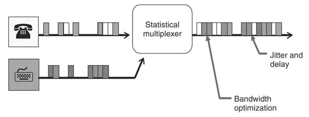
And when it comes to multiplexing several conversations on a single transmission line, instead of occupying a fraction of bandwidth all the time, ‘your’ bandwidth can be used by someone else while you are silent. This is known as ‘statistical multiplexing’.
The main advantage of statistical multiplexing is that it allows the bandwidth to be used more efficiently, especially when there are many conversations multiplexed on the same line (see companion book, Beyond VoIP protocols Chapter 5 for more details). But statistical multiplexing, as the name suggests, introduces uncertainty in the network. As just mentioned, in the case of TDM a delay of up to 125 μs could be introduced at each switch; this delay is constant throughout the conversation. The situation is totally different with statistical multiplexing (Figure 1.4): if the transmission line is empty when you need to send a chunk of data, it will go through immediately. If on the other hand the line is full, you may have to wait until there is some spare capacity for you.
The next generation telephone networks will use statistical multiplexing, and mix voice and data along the same transmission lines. Several technologies are good candidates (e.g., voice over frame relay, voice over ATM, and, of course, voice over IP).
We believe voice over IP is the most flexible solution, because it does not require setting up virtual channels between the sites that will communicate. VoIP networks scale much better than ATM or frame relay networks, and VoIP also allows communications to be established directly with VoIP endpoints: there is now a variety of IP-PBXs (private switches with a VoIP wide-area network interface), or IP phones on the market today that have no ATM or frame relay equivalent.
1.1.2 Voice and video over IP with RTP and RTCP
The Real-time Transport Protocol and Real-time Control Protocol, described in RFC 3550, are the protocols that have been used for the transport of media streams since the first conferencing tools were made available on the Internet. The visual audio tool (VAT) used RTP version 0. A description of version 1 is available at ftp://gaia.cs.umass.edu/pub/hgschulz/rtp/draft-ietf-avt-rtp-04.txt
Since then, RTP has evolved into version 2. RTPv2 is not backward compatible with version 1, and therefore all applications should be built to support RTPv2.
1.1.2.1 Why RTP/RTCP?
When a network using statistical multiplexing is used to transmit real-time data such as voice, jitter has to be taken into account by the receiver. Routers are good examples of such statistical multiplexing devices, and therefore voice and video over IP have to face the issue of jitter.
RTP was designed to allow receivers to compensate for jitter and desequencing introduced by IP networks. RTP can be used for any real-time (or more rigorously isochronous) stream of data (e.g., voice and video). RTP defines a means of formatting the payload of IP packets carrying real-time data. It includes:
- Information on the type of data transported (the ‘payload’).
- Timestamps.
- Sequence numbers.
Another protocol, RTCP, is very often used with RTP. RTCP carries some feedback on the quality of the transmission (the amount of jitter, the average packet loss, etc.) and some information on the identity of the participants as well.
RTP and RTCP do not have any influence on the behavior of the IP network and do not control quality of service in any way. The network can drop, delay, or desequence an RTP packet like any other IP packet. RTP must not be mixed up with protocols like RSVP (Resource Reservation Protocol). RTP and RTCP simply allow receivers to recover from network jitter and other problems by appropriate buffering and sequencing, and to have more information on the network so that appropriate corrective measures can be adopted (redundancy, lower rate codecs, etc.). However, some routers are actually able to parse IP packets, discover whether these packets have RTP headers, and give these packets a greater priority, resulting in better QoS even without any external QoS mechanism, such as RSVP for instance. Most Cisco® routers support the IP RTP PRIORITY command.
RTP and RTCP are designed to be used on top of any transport protocol that provides framing (i.e., delineates the beginning and end of the information transported), over any network. However, RTP and RTCP are mostly used on top of UDP (User Datagram Protocol).1 In this case, RTP is traditionally assigned an even UDP port and RTCP the next odd UDP port.2
1.1.2.2 RTP
RTP allows the transport of isochronous data across a packet network, which introduces jitter and can desequence the packets. Isochronous data are data that need to be rendered with exactly the same relative timing as when they were captured. Voice is the perfect example of isochronous data; any difference in the timing of the playback will either create holes or truncate some words. Video is also a good example, although tolerances for video are a lot higher; delays will only result in some parts of the screen being updated a little later, which is visible only if there has been a significant change.
RTP is typically used on top of UDP. UDP is the most widely used ‘unreliable’ transport protocol for IP networks. UDP can only guarantee data integrity by using a checksum, but an application using UDP has to take care of any data recovery task. UDP also provides the notion of a ‘port’, which is a number between 0 and 65,535 (present in every packet as part of the destination address) which allows up to 65,536 UDP targets to be distinguished at the same destination IP address. A port is also attached to the source address and allows up to 65,536 sources to be distinguished from the same IP address. For instance, an RTP over UDP stream can be sent from 10.10.10.10:2100 to 10.10.10.20:3200:
When RTP is carried over UDP, it can be carried by multicast IP packets, that is, packets with a multicast destination address (e.g. 224.34.54.23): therefore an RTP stream generated by a single source can reach several destinations; it will be duplicated as necessary by the IP network. (See companion book, Beyond VoIP Protocols, Chapter 6. IP multicast routing).
1.1.2.2.1 A few definitions
- RTP session: an RTP session is an association of participants who communicate over RTP. Each participant uses at least two transport addresses (e.g., two UDP ports on the
local machine) for each session: one for the RTP stream, one for the RTCP reports. When a multicast transmission is used all the participants use the same pair of multicast transport addresses. Media streams in the same session should share a common RTCP channel. Note that H.323 or SIP require applications to define explicitly a port for each media channel. So, although most applications comply with the RTP requirements for RTP and RTCP port sharing as well as the use of adjacent ports for RTP and RTCP, an application should never make an assumption about the allocation of RTP/RTCP ports, but rather use the explicit information provided by H.323 or SIP, even if it does not follow the RTP RFC guidelines. This is one of the most common bugs still found today in some H.323 or SIP applications.
- Synchronization source (SSRC): identifies the source of an RTP stream, identified by 32 bits in the RTP header. All RTP packets with a common SSRC have a common time and sequencing reference. Each sender needs to have an SSRC; each receiver also needs at least one SSRC as this information is used for receiver reports (RRs).
- Contributing source (CSRC): when an RTP stream is the result of a combination put together by an RTP mixer from several contributing streams, the list of the SSRCs of each contributing stream is added in the RTP header of the resulting stream as CSRCs. The resulting stream has its own SSRC. This feature is not used in H.323 or SIP.
- NTP format: a standard way to format a timestamp, by writing the number of seconds since 1/1/1900 at 0h with 32bits for the integer part and 32bits for the decimal part (expressed in 2132s (e.g., 0 × 80000000 is 0.5 s). A compact format also exists with only 16 bits for the integer part and 16 bits for the decimal part. The first 16 digits of the integer part can usually be derived from the current day, the fractional part is simply truncated to the most significant 16 digits.
1.1.2.2.2 The RTP packet
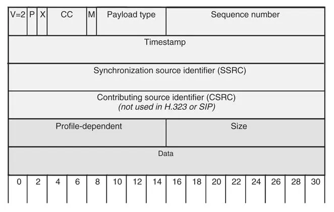
All fields up to the CSRC list are always present in an RTP packet (see Figure 1.6). The CSRC list may only be present behind a mixer (a device that mixes RTP streams, as defined in the RTP RFC). In practice, most conferencing bridges that perform the function of a mixer (H.323 calls them ‘multipoint processors’, or MPs) do not populate the CSRC list.
Here is a short explanation of each RTP field:
- Two bits are reserved for the RTP version, which is now version 2 (10). Version 0 was used by VAT and version 1 was an earlier IETF draft.
- A padding bit P indicates whether the payload has been padded for alignment purposes. If it has been padded (P = 1), then the last octet of the payload field indicates more precisely how many padding octets have been appended to the original payload.
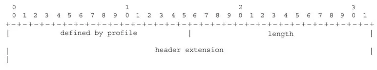
- An extension bit X indicates the presence of extensions after the eventual CSRCs of the fixed header. Extensions use the format shown in Figure 1.7.
- The 4-bit CSRC count (CC) states how many CSRC identifiers follow the fixed header. There is usually none.
- Marker (M): 1 bit. Its use is defined by the RTP profile. H.225.0 says that for audio codings that support silence suppress...