![]()
Chapter 1
Digital System Modeling and Simulation
1.1 Objectives
The objectives of the chapter are to:
- Describe digital systems
- Provide a brief history of digital systems
- Describe standard chips
- Describe custom-designed chips
- Describe programmable logic devices
- Describe field-programmable gated arrays
1.2 Modeling, Synthesis, and Simulation Design
Modeling and simulation have their roots in digital systems. Long before they became the basis of an interdisciplinary field, modeling and simulation were used extensively in digital system design. As electronic and computer technology advanced, so did modeling and simulation concepts. Today, the many computer-aided design (CAD) tools are pushing the limit of modeling, synthesis, and simulation technology. We focus on the implementation of modeling, synthesis, and simulation in digital systems.
A digital system is a system that takes digital signals as inputs, processes them, and produces digital output signals. A digital signal is a signal in which discrete steps are used to represent information and change values only at discrete (fixed) time intervals. In contrast, analog signals have “continuous” variations in signal amplitude over time. At a given instant of time, an analog signal has infinite possible values. A digital signal has discrete amplitude and time. Digital systems are very useful in the areas of signal processing (i.e., audio, images, speech, etc.), computing, communication, and data storage, among others. Digital systems are so commonplace in today's world that we tend to miss seeing them. Almost all electronic systems are partially or totally digitally based. Of course, real-world signals are all analog, and interfacing to the outside world requires conversion of a signal (information) from digital to analog. However, simplicity, versatility, repeatability, and the ability to produce large and complex (as far as functionality is concerned) systems economically make them excellent for processing and storing information (data).
1.3 History of Digital Systems
One of the earliest digital systems was the dial telephone system. Pulses generated by activating a spinning dial were counted and recorded by special switches in a central office. After all the numbers had been dialed and recorded, switches were set to connect the user to the desired party. A switch is a digital device that can take one of two states: open or closed.
In 1939, Harvard University built the Harvard Mark I, which went into operation in 1943. It was used to compute ballistic tables for the U.S. Navy. In the next few years, more machines were built in research laboratories around the world. The ENIAC (Electronic Numerical Integrator and Computer) was placed in operation at the Moore School of Electrical Engineering at the University of Pennsylvania, component by component, beginning with the cycling unit and an accumulator in June 1944. This was followed in rapid succession by the initiating unit and function tables in September 1945 and the divider and square-root unit in October 1945. Final assembly of this primitive computer system took place during the fall of 1945.
The first commercially produced computer was Univac I, which went into operation in 1951. More large digital computers were introduced in the next decade. These first-generation computers used vacuum tubes and valves as primary electronic components and were bulky, expensive, and consumed immense amounts of power. The invention of the transistor in 1948 at the Bell Telephone Laboratories by physicists John Bardeen, Walter Brattain, and William Shockley revolutionized the way that computers were built. Transistors are used as electrical switches that can be in the “on” or “off” state and so can be used to build digital circuits and systems. Transistors were used initially as discrete components, but with the arrival of integrated circuit (IC) technology, their utility increased exponentially. ICs are inexpensive when produced in large numbers, reliable, and consume much less power than do vacuum tubes. IC technology makes it possible to build complete digital building blocks into single, minute silicon “chips.” The size of transistors has been shrinking ever since their birth, and today, a complete computer is on one chip (microprocessor), and even large systems are being integrated into a single chip (system-on-a-chip).
1.4 Standard Logic Devices
Many commonly used logic circuits are readily available as integrated circuits. These are referred to as standard chips because their functionality and configuration meet agreed-upon standards. These chips generally have a few hundred transistors at most. They can be bought off-the-shelf, and depending on the application, the designer can build supporting circuitry on a PCB (printed circuit board) or breadboard. The advantages of using standard chips are their ease of use and ready availability. However, their fixed functionality has proved disadvantageous. Also, the fact that they generally do not have complex functionality means that many such chips have to be put together on a PCB, leading to a requirement for more area and components. Examples of standard chips are those in the 7400 series, such as the 7404 (hex inverters) and 7432 (quad two-input OR gates).
1.5 Custom-Designed Logic Devices
Chips designed to meet the specific requirements of an application are known as application-specific integrated circuits (ASICs) or custom-designed chips. The logic chip is designed from scratch. The logic circuitry is designed according to the specifications and then implemented in an appropriate technology. The main advantage of ASICs is that since they are optimized for a specific application, they perform better than do functionally equivalent circuits built from off-the-shelf ICs or programmable logic devices. They occupy very little area, as all of the logic can be built into one chip. Thus, less PCB area would be required, leading to some cost savings. The disadvantage of ASICs is that they can be justifiable economically only when there is bulk production of the ICs. Typically, hundreds of thousands of ASICs must be manufactured to recover the expenditures necessary in the design, manufacturing and testing stages. Another drawback of the custom-design approach is that it requires the work of highly skilled engineers in the design, manufacturing, and test stages. The design time needed for these chips is also high, as a lot of verification has to be carried out to check for correct functionality. The circuitry in the chip cannot be altered once it is fabricated.
1.6 Programmable Logic Devices
Advances in VLSI technology made possible the design of special chips, which can be configured by a user to implement different logic circuits. These chips, known as programmable logic devices (PLDs), have a very general structure and contain programmable switches, which allow the user to configure the internal circuitry to perform the desired function. The programmer (end user) has simply to change the configuration of these switches. This is usually done by writing a program in a hardware description language (HDL) such as VHDL or Verilog and “downloading” it into the chip. Most types of PLDs are reprogrammable for a fixed number of times (generally, a very high number). This makes PLDs excellent for use in prototyping of ASICs and standard chips. A designer can program a PLD to perform a particular function and then make changes and reprogram it for retesting on the same chip. Also, there is a great cost savings in using a device that is reprogrammable for prototyping purposes. The main disadvantage of PLDs is that they may not be the best performing. The performance of a functionally equivalent ASIC or standard chip is likely to be better. This is because all functions have to be realized from existing blocks of logic inside the PLD. The most popular types of PLDs include:
- Simple programmable logic devices (SPLDs)
- Programmable array logic (PAL)
- Programmable logic array (PLA)
- Generic array logic (GAL)
- Complex programmable logic devices (CPLDs)
- FPGA (field-programmable gate arrays)
- FPIC (field-programmable interconnect)
These different types of PLDs vary in their internal architectures. Different manufacturers of PLDs choose different architectures for implementing the logic blocks and the programmable interconnection switch matrices. FPGAs have the highest gate count among the various PLDs, which can accommodate much larger designs than can SPLDs and CPLDs. Today's FPGAs have millions of transistors in one chip. PALs and PLAs generally carry just a few hundred or a few thousand gates. PLD manufacturers include, among others, Altera Corporation, Xilinx Inc., Lattice Semiconductor, Cypress Semiconductor, Atmel, Actel, Lucent Technologies, and QuickLogic.
1.7 Simple Programmable Logic Devices
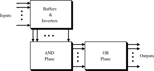
Simple programmable logic devices (SPLDs) include programmable logic arrays (PLAs) and programmable array logic (PALs). Early SPLDs were simple and consisted of an array of AND gates driving an array of OR gates. An AND gate (known as an AND plane or AND array) feeds a set of OR gates (an OR plane). This helps in realizing a function in the sum-of-products form.
Figure 1.1 shows the general architecture of PLAs and PALs. The most common housing of PLAs and PALs was a 20-pin dual-in-line package (DIP). The difference between PALs and PLAs is that in PLA, both the AND and OR planes are programmable, whereas in PALs, the AND plane is programmable but the OR plane is fixed. PLAs were expensive to manufacture and offered somewhat poor performances, due to propagation delays. Therefore, PALs were introduced for their ease of manufacturability, lower cost of production, and better performance. PALs usually contain flip-flops connected to the OR gates to implement sequential circuits. Both PLAs and PALs use antifuse switches, which remain in a high-impedance state until programmed into a low-impedance (fused) state. These devices are generally programmed only once. Generic array logic devices (GALs) are similar to PALs but can be reprogrammed. PLAs, PALs, and GALs are programmed using a PAL programmer device (a burner).
1.8 Complex Programmable Logic Devices
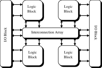
PALs and PLAs are useful for small digital circuits which do not require more than 32 inputs and outputs. To implement circuits that need more inputs and outputs, multiple PLAs or PALs can be used. However, this will compromise the performance of the design and also occupy more area on the PCB. In such situations, a complex programmable device (CPLD) would be a better choice. A CPLD comprises multiple circuit blocks on a single chip. Each block is similar to a PLA or PAL. There could be as few as two such blocks in a CPLD and 100 or more such blocks in larger CPLDs. These logic blocks are interconnected through a programmable switch matrix or interconnection array, which allows all blocks of the CPLD to be interconnected. Figure 1.2 shows the internal structure of a CPLD. As a result of this configuration, the architecture of the CPLD is less flexible. However, the propagation delay of a CPLD is predictable. This advantage allowed CPLDs to emulate ASIC systems, which operate at higher frequencies.
1.9 Field-Programmable Gate Arrays
Field-programmable gate arrays (FPGAs) differ from the other PLDs and generally offer the highest logic capacity. An FPGA consists of an array of complex logic blocks (CLBs) surrounded by programmable I/O blocks (IOBs) and connected by a programmable interconnection network. The IOBs provide the control between the input–output package pins and the...