eBook - ePub
Cardiac Pacemakers and Resynchronization Step by Step
An Illustrated Guide
- English
- ePUB (mobile friendly)
- Available on iOS & Android
eBook - ePub
Cardiac Pacemakers and Resynchronization Step by Step
An Illustrated Guide
About this book
This new edition of the bestselling step-by-step introduction to cardiac pacemakers now includes additional material on CRT and an accompanying website. It retains the effective use of full-page illustrations and short explanations that gained the book such enormous popularity and now provides information on recent advances in cardiac pacing, including biventricular pacing for the treatment of heart failure.
Trusted by 375,005 students
Access to over 1.5 million titles for a fair monthly price.
Study more efficiently using our study tools.
Information
Cardiac Pacing
Implantation
A pacemaker (also known as a pulse generator) is a device that delivers electrical stimuli over leads with electrodes in contact with the heart. The lithium-iodine battery is sealed in a titanium can and provides electricity out of a chemical reaction. The pacemaker is like a little computer. The epoxy connector block on top of the pacemaker makes the connection from lead to pacemaker. The lead is an insulated wire. There are two types of leads: bipolar, with the two electrodes embedded inside the heart, and unipolar, where only one electrode is inside the heart, and the pacemaker can acts as the other electrode. Both types are widely used. In both types, the tip electrode is virtually always the negative pole or cathode. Virtually all pacemakers are implanted transvenously under local anesthesia using either the cephalic vein exposed by cutdown or percutaneous puncture of the subclavian vein. The leads are passed to the right side of the heart under x-ray vision (fluoroscopy). More recently, for the treatment of heart failure, the left ventricle may be paced by insertion of a lead into a tributary of the coronary sinus, a venous structure on the epicardial surface of the left ventricle. The pacemaker pocket is fashioned over the pectoralis major muscle below the collarbone. True epicardial leads require thoracic surgery and are used only when there is no venous access.
Basic Function
The pacing lead functions as a “two-way street” for the transmission of electricity to the heart for pacing as well as for the sensing of spontaneous cardiac electric activity from the heart to the pacemaker. The operative techniques and intraoperative measurements are straightforward compared to the technical knowledge required to understand the electrophysiology of pacing and follow-up of patients for the best use of the important programmable functions. The function of an implanted pacemaker can be altered by means of a programmer, which is a kind of a dedicated desktop computer. A modern pacemaker lasts 7–10 years. When the battery is depleted, the entire pacemaker (excluding the leads) is replaced.
Power Source
The lithium–iodine battery is the gold standard of pacemaker power sources, and the only one presently used in pacemakers. The battery has a long shelf life and is hermetically sealed to protect the electronic components of the pacemaker. In lithium–iodine batteries, lithium is the anode and iodine the cathode. When delivering electric current, this battery progressively develops a slow rise in internal resistance that can be measured by telemetry. The rising battery impedance causes a fairly linear drop in cell voltage, translated by design into a gradual decline in the pacing rate reflecting the status of the battery. The battery retains a satisfactory voltage for 90% of its life. Battery capacity (expressed in amperehours, Ah) is the quantity that expresses the longevity of a lithium–iodine battery. A pacemaker generally holds a capacity between 0.8 and 2.5 Ah.
The current drain from the battery (expressed in μA) is utilized to produce the stimulus and to feed the various sensing, detection, and “housekeeping” electronic circuits. The output voltage of a fresh cell is 2.8 volts (V). The cell voltage at the elective replacement point is 2.2–2.4 V. The pacemaker replacement time can be determined by measuring the pacemaker rate upon application of a magnet or the battery voltage and/or impedance by telemetry with the programmer.
Reminder
The pacemaker (or pacing) stimulus is also known as a spike, an artifact, or an output pulse.
Caveat
Do not confuse cathode with anode! The terminology of the battery terminals appears different from that of the load. For the battery the anode is the negative electrode where electrons are freed from lithium atoms and positive lithium ions are produced. In the battery the cathode is the positive terminal where free electrons rebind with iodine to form negative iodide ions. At the load, the cathode is the negative terminal and the anode is the positive one. The connection of battery to circuit is simple: positive-to-positive and negative-to-negative. Remember that the anode of the battery or load is where the electrons leave. The cathode of both battery and load is where the electrons enter. It is as simple as that! These are the universal definitions found in all good books about electricity and/or electronics. It is not true that the anode and cathode of the battery are reversed by convention. The only convention is that the electric current flows from positive to negative.
Rate or Interval?
The pacemaker, design engineers, and the medical staff all “think” in terms of intervals rather than rate. We should do away with rate when defining timing cycles. Rate is a relatively simple designation during continuous pacing or continuous inhibition but it is of little value and confusing if pacing and sensing alternate. Yet, for ease of programming, manufacturers have expressed parameters in terms of rate rather than interval. Programmed rates may also be useful when communicating with the patient or anyone with little knowledge of pacing. The abbreviation bpm refers to beats per minute of the intrinsic heart rate and ppm refers to the paced rate. However, these abbreviations are often used interchangeably.
Caveat
Peculiar rhythms are created by ECG machines and Holter recorders functioning at an incorrect speed. In a Holter recording, intermittent slowing of the recording will cause a pseudotachycardia. The diagnosis is evident when the QRS and T waves are too narrow when compared to those recorded at normal speed. Conversely, a faster speed will cause pseudobradycardia, with excessively long AV delays or PR intervals as well as QRS complexes.
Single Chamber Pacemakers
VOO mode
A VOO pacemaker generates stimuli with no relationship to the spontaneous rhythm. The VOO mode is labeled “fixed-rate” or asynchronous. The competitive stimuli will capture the ventricle only when they fall outside the absolute refractory period of the ventricle that follows spontaneous beats. The VOO mode is now obsolete, and it is used only for testing purposes by applying a magnet over the pacemaker. Ventricular fibrillation induced by a competitive pacemaker stimulus falling in the ventricular vulnerable period (the R-on-T phenomenon) is very rare outside of circumstances such as myocardial ischemia or infarction, electrolyte abnormalities, or autonomic imbalance. Indeed, transtelephonic transmission of the electrocardiogram with a magnet over a pacemaker is quite safe.
VVI mode
A VVI pacemaker senses the intracardiac ventricular depolarization or electrogram which is recorded by measuring the potential (voltage) difference between the two electrodes (anode and cathode) used for pacing. A VVI pacemaker has an internal clock or lower rate timing cycle that begins with a paced (VP) or sensed ventricular event (VS). The initial portion of the cycle (after VP or VS) consists of the ventricular refractory period (VRP, usually 200–350 ms), during which the pacemaker cannot sense any signals. More specifically, any signal during the refractory period cannot initiate a new lower rate interval (LRI). Beyond the VRP, a sensed ventricular event inhibits the pacemaker and resets the LRI, so that the timing clock returns to baseline. A new pacing cycle is reinitiated, and if no event is sensed the timing cycle ends with the release of a ventricular stimulus according to the LRI. The sensing function prevents the competition between pacemaker and intrinsic rhythm seen with VOO pacing. Hence the old term “demand pacemaker” for a VVI pacemaker, to describe the delivery of a stimulus when the spontaneous rate is less than the lower rate of the pacemaker.
Caveats
1. When a patient presents with an ECG showing no pacemaker stimuli, the pacing function should be tested by the application of a pacemaker magnet, which converts any pacemaker to the fixed-rate or asynchronous mode (VVI to VOO). One should refrain from performing carotid sinus massage (a vagal reflex producing sinus node slowing and AV block) in this situation, because it may cause prolonged bradycardia resulting in the delivery of pacemaker stimuli that may or may not be capable of capture. It is safer to first establish effective pacing with magnet application.
2. The stimulus-to-stimulus interval (automatic interval) is usually equal to the escape interval, which is measured electronically from the time of intracardiac sensing to the succeeding stimulus. In practice, the escape interval is measured from the onset of the sensed QRS complex in the surface ECG. The escape interval measured in this way must necessarily be longer than the electronic escape interval, because intracardiac sensing takes place a finite time after the onset of the surface ECG. Thus, if the QRS complex is wide and intracardiac sensing occurs 90 ms from the beginning of the surface ECG, the measured escape interval (with calipers) will be 90 ms longer than the programmed automatic interval.
Hysteresis
In hysteresis the electronic escape interval is longer than the automatic interval. Its purpose is to maintain sinus rhythm and atrioventricular (AV) synchrony for as long as possible at a spontaneous rate lower (e.g. 50 bpm) than the automatic rate of the pacemaker (e.g. 70 ppm). Thus when the spontaneous rate drops below 50 bpm, the pacemaker will take over at 70 ppm. It will continue to pace at 70 ppm until the spontaneous rate exceeds the automatic rate, i.e., when the spontaneous QRS complex occurs within the 857 ms automatic interval.
If the search hysteresis feature is enabled, the pacemaker will periodically reduce the lower pacing rate for a few cycles by a programmable value in order to reveal potential intrinsic activity below the programmed lower rate or sensor rate. Hysteresis will remain active when intrinsic activity is sensed during the search period. If there is no intrinsic activity during the search, pacing resumes at the lower rate, or the sensor-indicated rate.
Caveat
Do not misinterpet hysteresis for oversensing with pauses.
Symbolic representation of pacemaker events and basic measurements
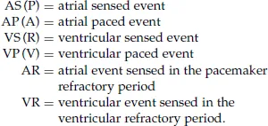
Some devices depict a ventricular premature complex as a VPC or PVC. The refractory period is defined below. The intervals between events are measured by electronic calipers.
Timing cycles are expressed in milliseconds (ms):

The 60,000 rule is useful in converting rate to intervals:
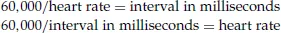
A pacemaker rate of 70 ppm gives an interval of 857 ms
bpm = beats per minute, which refers to the rate of a spontaneous rhythm. ppm = pulses per minute, which refers to the rate of a pacemaker. These designations are often used interchangeably.
bpm = beats per minute, which refers to the rate of a spontaneous rhythm. ppm = pulses per minute, which refers to the rate of a pacemaker. These designations are often used interchangeably.
Other single chamber pacemakers
A VVT pacemaker releases a ventricular stimulus immediately upon sensing, which is the opposite of inhibition with the VVI mode. The VVT mode requires three timing intervals: LRI and VRP, like the VVI mode, but additionally an upper rate interval (URI) to limit the maximum paced ventricular rate in response to ventricular sensing of rapidly occurring potentials. Upon sensing a QRS complex the pacemaker immediately discharges a stimulus (w...
Table of contents
- Cover
- Half Title Page
- Series
- Title Page
- Copyright
- Preface to the First Edition
- Preface to the Second Edition
- Abbreviations
- Color Plate Section
- Cardiac Pacing
- Cardiac Resynchronization (CRT)
- Appendix: Guidelines
- Further Reading
- Index
Frequently asked questions
Yes, you can cancel anytime from the Subscription tab in your account settings on the Perlego website. Your subscription will stay active until the end of your current billing period. Learn how to cancel your subscription
No, books cannot be downloaded as external files, such as PDFs, for use outside of Perlego. However, you can download books within the Perlego app for offline reading on mobile or tablet. Learn how to download books offline
Perlego offers two plans: Essential and Complete
- Essential is ideal for learners and professionals who enjoy exploring a wide range of subjects. Access the Essential Library with 800,000+ trusted titles and best-sellers across business, personal growth, and the humanities. Includes unlimited reading time and Standard Read Aloud voice.
- Complete: Perfect for advanced learners and researchers needing full, unrestricted access. Unlock 1.5M+ books across hundreds of subjects, including academic and specialized titles. The Complete Plan also includes advanced features like Premium Read Aloud and Research Assistant.
We are an online textbook subscription service, where you can get access to an entire online library for less than the price of a single book per month. With over 1.5 million books across 990+ topics, we’ve got you covered! Learn about our mission
Look out for the read-aloud symbol on your next book to see if you can listen to it. The read-aloud tool reads text aloud for you, highlighting the text as it is being read. You can pause it, speed it up and slow it down. Learn more about Read Aloud
Yes! You can use the Perlego app on both iOS and Android devices to read anytime, anywhere — even offline. Perfect for commutes or when you’re on the go.
Please note we cannot support devices running on iOS 13 and Android 7 or earlier. Learn more about using the app
Please note we cannot support devices running on iOS 13 and Android 7 or earlier. Learn more about using the app
Yes, you can access Cardiac Pacemakers and Resynchronization Step by Step by S. Serge Barold,Roland X. Stroobandt,Alfons F. Sinnaeve in PDF and/or ePUB format, as well as other popular books in Medicine & Physiology. We have over 1.5 million books available in our catalogue for you to explore.