The ultimate dream of every software-defined radio (SDR) front-end architect is to deliver a radio-frequency (RF) transceiver that can be reconfigured into every imaginable operating mode, in order to comply with the requirements of all existing and even upcoming communication standards. These include a large range of modes for cellular (2G–2.5G–3G and further), WLAN (802.11a/b/g/n), WPAN (Bluetooth, Zigbee, etc.), broadcasting (DAB, DVB, DMB, etc.), and positioning (GPS, Galileo) functionalities. Obviously, each of them has different center frequency, channel bandwidth, noise levels, interference requirements, transmit spectral mask, and so on. As a consequence, the performances of all building blocks in the transceiver must be reconfigurable over an extremely wide range, requiring ultimate creativity from the SDR designer.
Reconfigurability is a requirement for SDR functionality, but often one forgets that it can also be an enabler for low power consumption. Indeed, once flexibility is built into a transceiver, it can be used to adapt the performance of a radio to the actual circumstances instead of those implied by the worst-case situation of the standard. Since linearity, filtering, noise, bandwidth, and so on, can be traded for power consumption in the SDR, a smart controller is able to adapt the radio at runtime to the actual performance required, and hence can reduce the average power consumption of the SDR.
In this chapter, several important innovations and concepts are presented that bring this ultimate dream closer to reality. These include circuits for wideband local oscillator (LO) synthesis, multifunctional receiver and transmitter blocks, and novel ADC (analog-to-digital converter) implementations. The result of all this is integrated in the world’s first SDR transceiver covering the frequency range from 174 MHz to 6 GHz, implemented in a 1.2-V 0.13-μ CMOS technology.
1.2 SYSTEM-LEVEL CONSIDERATIONS
A first choice to be made is the radio architecture to be used. In past decades, lots of studies and examples have been presented on heterodyne, homodyne, low-IF (intermediate frequency), wideband-IF, and other architectures, all having certain benefits and problems for a certain application. Which one to choose? In view of SDR, this question perhaps becomes a little easier to answer. Indeed, when the characteristics of all possible standards are taken into account, not a single intermediate frequency can be found that suits them all. And having multiple IFs and the associated (external) filtering stages increases the hardware cost of the SDR, which cannot be tolerated. So direct-conversion architectures are the right choice for the job. All of the well-known problems, such as dc offsets, I/Q mismatch, 1/f noise, and power amplifier (PA) pulling, that have limited the proliferation of zero-IF CMOS radios into mainstream products have been better understood in recent years, and it will enable the design of a low-cost front end.
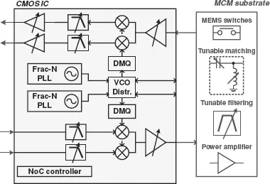
A schematic vision of what the final SDR will look like is represented in Fig. 1.1. For a low cost in a large-volume consumer market, the active transceiver core is implemented in a plain CMOS technology. It includes a fully reconfigurable direct-conversion receiver, transmitter, and two synthesizers [for frequency-domain duplex (FDD) operation]. The functions that cannot be implemented in CMOS are included on the package substrate. These are related primarily to the interface between the active core and the antenna. They must provide high-Q bandpass filtering or even duplexing, impedance-matching circuits, and power amplification. In the remainder of the chapter we focus primarily on the transceiver implementation.
FIGURE 1.1 Conceptual view of an SDR transceiver front end.
The hard works starts with determining performance specifications for each block in the chain. The total budget for gain, noise, linearity, and so on, must be divided over all blocks, ensuring that all possible test cases are covered, and this must be done for every standard. Having very flexible building blocks helps a great deal, of course, but making a smart system analysis at this point is crucial to obtaining an optimal SDR solution.
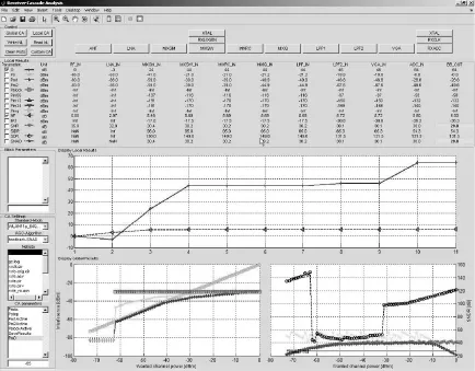
A custom MATLAB tool has been developed to do this exercise [1]. It takes in a netlist that describes all building blocks, with the performance characteristics and gain ranges, and simulates on a behavioral level the complete chain for a list of different test cases. Figure 1.2 shows a screenshot. The performance under all circumstances can thus be evaluated, and the building block performance can be tuned to fulfill all requirements. Gain ranges and signal filtering must be set such that the signal levels are an optimal trade-off between noise and distortion. Although being a difficult exercise, the analysis can show that with the built-in flexibility, a software-defined radio can achieve state-of-the-art performance very close to that of dedicated single-mode solutions. In the next sections we go deeper into the design of some crucial building blocks.
FIGURE 1.2 System-level analysis tool.
1.3 WIDEBAND LO SYNTHESIS
To generate all required LO signals in the range 0.1 to 6 GHz, several frequency-generation techniques have been proposed to relax the tuning range specifications of a voltage-controlled oscillator (VCO). They use division, mixing, multiplication, or a combination of these [2]. However, to make these systems efficient in terms of phase noise and power consumption, the VCO tuning range still has to be maximized. In the following section we discuss the design of such a wideband VCO, and the architecture required to generate all LO signals is discussed in Section 1.3.2. The target frequency band of the VCO is around 4 GHz, so that it does not coincide with any of the major RF frequency bands used. The actual LO frequency will be obtained by further division and mixing. Since the VCO frequency differs from the RF frequency, most direct-conversion problems will be relaxed or avoided.
1.3.1 3 to 5-GHz Voltage-Controlled Oscillator
To reach the stringent phase noise specifications for today’s mobile communication systems, most RF transceiver integrated circuits (ICs) use LC-VCOs. Frequency tuning of LC VCOs is commonly done by changing the capacitance value of the resonant tank using varactors and/or an array of switched capacitors [3]. Switched or controlled inductor designs have been reported [4], but it remains difficult to cover the desired wideband continuously and to limit the deterioration of the phase noise performance caused by the insertion of these switches.
Instead of using a single large varactor to tune the frequency, a mixed discrete/ continuous tuning scheme is usually chosen [3]. A small varactor is used for fine continuous tuning, and larger steps are realized by digitally switching capacitors in and out of the resonant tank. This has two advantages: The VCO gain is lower, allowing easier phase-locked loop (PLL) design, and digitally switched varactors have a higher ratio between the capacitance in the on-state (C_on) and the capacitance in the off-state (Coff). A higher Con/Coff ratio allows a larger VCO frequency tuning range. However, as the tuning range of a VCO is increased and exceeds the typical 20% range obtained in many designs, new problems and trade-offs appear that need a solution. In this design we have tackled the two main problems encountered in wideband LC-VCOs [5]. First, the negative resistance required to maintain oscillation varies a lot over the frequency range, leading to significant overhead when a fixed active core is used. Second, the large variation of the VCO gain (KVCO) across the entire tuning range creates problems for optimal and stable PLL design. Solutions are proposed for both problems.
1.3.1.1 Tank Loss Variations In the target frequency range ( < 5 GHz), the losses in the oscillator tank are usually dominated by the inductor. It can be modeled by an inductor series resistance RS, which in this simple example we consider to be frequency independent. This simplification is, of course, not completely valid, since extra losses due to the skin effect, for examples will increase the resistance at higher frequencies, but that does not change the general conclusion we will make.
The negative resistance needed to compensate for the inductor losses is given by Gm = RS (ω C)2, where C is the total tank capacitance and ω is the oscillation frequency, which is, of course, given by the simple equation
, with L the inductance value [6]. If we want the oscillation frequency to change by a factor of 2, for example, the total capacitance of the resonant tank has to be changed by a factor of 4, and hence the required negative resistance must also change by a factor of 4. The transconductance required for the active core is four times higher at the lower end of the frequency tuning range than at the higher end.
Recent phase noise theory based on the impul...
Table of contents
Cover
Half Title page
Title page
Copyright page
Preface
Contributors
Part I: Transceiver Concepts and Design
Part II: Receiver Design
Part III: Transmitter Techniques
Part IV: Digital Signal Processing for RF Transceivers
Index
Frequently asked questions
Yes, you can cancel anytime from the Subscription tab in your account settings on the Perlego website. Your subscription will stay active until the end of your current billing period. Learn how to cancel your subscription
No, books cannot be downloaded as external files, such as PDFs, for use outside of Perlego. However, you can download books within the Perlego app for offline reading on mobile or tablet. Learn how to download books offline
Perlego offers two plans: Essential and Complete
Essential is ideal for learners and professionals who enjoy exploring a wide range of subjects. Access the Essential Library with 800,000+ trusted titles and best-sellers across business, personal growth, and the humanities. Includes unlimited reading time and Standard Read Aloud voice.
Complete: Perfect for advanced learners and researchers needing full, unrestricted access. Unlock 1.5M+ books across hundreds of subjects, including academic and specialized titles. The Complete Plan also includes advanced features like Premium Read Aloud and Research Assistant.
Both plans are available with monthly, semester, or annual billing cycles.
We are an online textbook subscription service, where you can get access to an entire online library for less than the price of a single book per month. With over 1.5 million books across 990+ topics, we’ve got you covered! Learn about our mission
Look out for the read-aloud symbol on your next book to see if you can listen to it. The read-aloud tool reads text aloud for you, highlighting the text as it is being read. You can pause it, speed it up and slow it down. Learn more about Read Aloud
Yes! You can use the Perlego app on both iOS and Android devices to read anytime, anywhere — even offline. Perfect for commutes or when you’re on the go. Please note we cannot support devices running on iOS 13 and Android 7 or earlier. Learn more about using the app
Yes, you can access Multi-Mode / Multi-Band RF Transceivers for Wireless Communications by Gernot Hueber, Robert Bogdan Staszewski, Gernot Hueber,Robert Bogdan Staszewski in PDF and/or ePUB format, as well as other popular books in Technology & Engineering & Mobile & Wireless Communications. We have over 1.5 million books available in our catalogue for you to explore.