A comprehensive overview of the possibilities and potential of X-ray scattering using nanofocused beams for probing matter at the nanoscale, including guidance on the design of nanobeam experiments. The monograph discusses various sources, including free electron lasers, synchrotron radiation and other portable and non-portable X-ray sources.
For scientists using synchrotron radiation or students and scientists with a background in X-ray scattering methods in general.
eBook - ePub
Nanobeam X-Ray Scattering
Probing Matter at the Nanoscale
- English
- ePUB (mobile friendly)
- Available on iOS & Android
eBook - ePub
Nanobeam X-Ray Scattering
Probing Matter at the Nanoscale
About this book
Trusted by 375,005 students
Access to over 1.5 million titles for a fair monthly price.
Study more efficiently using our study tools.
Information
1
Introduction
When Wilhelm Conrad Röntgen discovered “a new kind of rays” in 1895 [1], they became famous very soon for their remarkable property of penetrating without deviation through almost any kind of matter. They get weakened depending on material, the lighter the material, the less the absorption, this was clear very soon. Almost immediately this penetrating power was used to look inside materials without the need to physically destroy them. More than a century after the discovery, X-rays (in German-speaking countries they are called “Röntgenstrahlen” after their discoverer, although W.C. Röntgen himself called them “X-Strahlen”, X-rays) are still famous for the same reason. Their applications in medical and technical imaging are still mainly governed by looking into the interior of materials, be it a suitcase in an X-ray scanner at the airport, an engine part in quality control, or a human body in a hospital. X-rays play a vital role also in material science, as they provide precious information about the otherwise inaccessible material’s interior.
1.1 X-ray Interaction with Matter
1.1.1 Transmission of X-ray
From a physical point of view, we nowadays understand a bit more than Mr. Röntgen did. The fact that X-rays go through matter without deviation means that the refractive index is very close to unity. A small imaginary part in the refractive index accounts for absorption. Looking very carefully reveals that even the real part of the refractive index is not exactly unity, but slightly smaller. This is the origin of the process of total external reflection: When X-rays hit a surface under very small angles, they may bounce off like from a mirror. This happens up to a certain critical angle for total external reflection, which depends on the density of the material and on the wavelength of the X-rays. Typical values of the difference between the refractive index of X-rays and vacuum (or air) are in the order of 10–5, with the imaginary part of that difference about an order of magnitude smaller.
In modern X-ray science, the X-ray transmission as shown in Figure 1.1a is still used in the important field of X-ray imaging, with a spatial resolution limited mainly by the resolution of the detector. The traditionally used photographic films or image plates have mostly been replaced by two-dimensional (2D) detector arrays, which are based on different detection principles, but have in common that the image is obtained in the form of intensity values per pixel. To increase the image resolution, often optical detectors with magnifying optics are used, and resolutions down to about a micrometer are reached. In this case the X-rays are collected on a fluorescent screen placed at the focus of the objective. Such a transmission image, however, often does not contain enough information about the specimen, since the absorption information is roughly the projection (or the integration) of the absorption of the whole specimen along the X-ray beam direction. It is not possible to discern whether higher absorption detected in a certain part of the specimen is related to a heavier material or an increased thickness. In order to improve this technique, three major developments have demonstrated to be very effective: three-dimensional (3D) information can be obtained using tomographic approaches, where several 2D images recorded at different view angles are combined to obtain the full 3D distribution of the absorption contrast inside the sample. Taking measurements at different wavelengths allows distinguishing differences in thickness and absorption inside the specimen. Finally, not only using the absorption, that is, the imaginary part of the refractive index, but also exploiting the real part of the refractive index leads to what is know as “phase contrast imaging”. Due to the real part of the refractive index, X-rays inside the material have a slightly different wavelength, and consequently the transmitted X-rays behind the sample experience a phase shift, which depends on the amount and density of traversed material for each lateral position, as shown in Figure 1.1b. These phase shifts lead to interference effects, which can produce a very significant imaging contrast even in cases where the absorption contrast is weak, especially for light materials such as biological tissue. Phase contrast imaging benefits from the fact that the deviation of the real part of the refractive index from unity is typically an order of magnitude larger than the imaginary part.
1.1.2 Diffraction of X-rays
Several years after the discovery of X-rays, Walter Friedrich and Paul Knippig under the supervision of Max von Laue proved that X-rays are diffracted from the regular arrangement of atoms in a crystal [2]. It was a rather remarkable experiment performed in 1912 that proved, at the same time, the wave nature of X-rays and the fact that crystals are built from atoms. Even more, the distances of the atoms and the wavelength of the X-rays used were shown to be of the same order of magnitude, around 1 Å (or, in SI unit, 0.1 nm; the Å-scale is, however, still largely used in the X-ray scattering community). Ever since, scattering of X-rays has been used for the analysis of crystalline materials. This is a rather different way of obtaining information on the interior of a material as compared to the absorption measurements mentioned above. There is no a priori resolution in realspace, since a beam of size typically ranging from few hundred micrometers to few millimeters is directed onto a crystal, and is diffracted under large angles. The detector collects the intensity diffracted by the whole illuminated volume, with no lateral resolution. Nevertheless, from the diffraction angle the distances between the atoms inside the specimen can be measured very accurately, up to 1/10 000 of the diameter of a single atom [3, 4]. This indeed represents a resolution far beyond any other microscopy technique, which, of course, comes at a price – it requires a crystalline specimen with a regular arrangement of atoms over very large distances. Therefore, this seems to be a technique with not too many applications, since large perfect crystals are rare. The opposite is true. Almost all solid state material is crystalline at least on a mesoscopic scale, that is, it consists of many small crystallites with size often in the micrometer or sometimes sub-micrometer range. This is still large compared to interatomic distances, and therefore diffraction can occur. By measuring accurately the diffraction patterns from a specimen, not only the distances between atoms but also the symmetry of the atomic arrangement can be determined. This provides a fingerprint of the material, and hence allows to determine the constituents of alloys, the nature of pigments in a painting, the constituents of compounds, to cite a few examples. The measurement of atomic distances also results in sensitivity to strain, for example due to distortions in the crystal lattice around defects or near interfaces.
Figure 1.1 (a) X-rays travelling through matter (gray) is exponentially weakened due to the imaginary part of the refractive index. Different materials can be distinguished by different amplitudes and hence different intensities behind the sample. (b) The deviation from unity of the refractive index leads to a wavelength change inside matter (gray), even in the case of zero absorption. This leads to relative phase shifts of the X-rays after the sample, which can be exploited in phase contrast imaging, using the interference of waves transmitted through different parts of the sample.
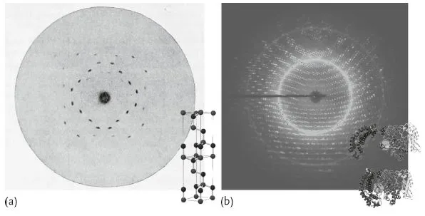
The year this manuscript has been prepared coincides with the centenary of the first recorded X-ray diffraction image by von Laue in 1912, who was awarded the Nobel Prize in 1914. In the past 100 years, X-ray diffraction techniques have revolutionized our understanding of – amongst others – condensed matter. This is illustrated in Figure 1.2a, showing one of the first Laue images of a zinc-blende crystal and the rather simple unit cell structure, which required, however, quite some intuition to reveal at those days. For comparison a recent diffractogram of a crystal of the macromolecule collagenase G is shown as well, taken using monochromatic synchrotron radiation. From large series of such datasets, the structure of the molecule (consisting of many thousand atoms) can be determined, and even its biological functionality – in this case degeneration of collagen molecules – understood [6]. The inset of Figure 1.2b shows two according conformations (only the most important structural elements of the molecule are shown). Actually, X-ray diffraction has become an extremely important technique for such investigations of biological macromolecules and their function, which are nowadays performed on a routine basis. The first time X-ray diffraction helped to understand macromolecular structure might also be the most famous example of such investigations, namely the solution of the DNA molecule [7, 8], certainly one of the greatest contributions of X-rays to the understanding of nature.
Figure 1.2 (a) One of the first Laue images of a zinc-blende crystal ([5]; image from [5]), the inset shows two unit cells of the according crystal structure. (b) Recent diffractogram of a crystal formed by a complex macromolecule collagenase G. The inset shows a simplified structural view of the molecule in two configurations, corresponding to two phases in the hydrolysis of a collagen triple-helix molecule. Image courtesy of H. Brandstetter, see also [6].
A very important class of crystals in everyday life are semiconductors, which are actually the most perfect crystals surrounding us. The use of semiconductors in nanotechnology demands more and more detailed structural analysis at the nanoscale to correlate with physical properties and materials functionality. Diffraction techniques continue to develop at a rapid pace and strongly contribute to reveal the complex properties of materials also at the nanoscale, where crystal structure, morphology, chemical composition and crystalline defects and distortions (strain fields) all come into interplay.
Diffraction, however, is not limited to the investigation of atomic-scale distances, but can serve the investigation of nano- and microscale structures as well. Depending on the wavelength used, or the diffraction angles explored, one can access crystal structure at the atomic scale (including, crystallographic phases, strain fields, intermixing in alloys, etc.) but also order or periodicities at the mesoscale. Due to the fact that the interaction of X-rays with matter is mediated by electrons, and that the phenomenon of diffraction is based on a constructive interference of waves related to “some” periodicity of the electronic structure, any and all repeated distances in a specimen (thickness, lateral size, lateral ordering) can give rise to “diffraction”. One can say that, qualitatively, the diffraction process picks up a “specific distance” in real-space, and transforms it into a defined “frequency” in reciprocal space. In other words, the diffraction from a real-space structure corresponds to measure its Fourier transform. Each observed frequency k corresponds to a periodicity d ~ 1/ k in real-space. Matter is often a patchwork of different lengthscales, especially so in nanostructured materials, both natural as well as technical ones. Important examples are tissues like wood or bone, or technical alloys with a strength depending on the constituent nanocrystalline particles and how they are interlinked. The surface of such particles and interfaces between them are often most important for the properties, and it is safe to say that sometimes the particular structure of a certain interface is even more important than the material on both sides of it. For the understanding of material properties out of its inner structure, the characterization of nanostructures, especially including the properties of surfaces and interfaces, is therefore a central task.
1.1.3 X-ray Elemental Sensitivity
By tuning the energy of the X-rays one can promote electrons from the atomic core levels to excited states. When these excited states decay, X-rays with a specific wavelength are emitted isotropically in the space. This “fluorescence” effect can be used to probe composition of materials, and can be exploited in imaging techniques to have an elemental map of the investigated specimen. Energy tunability is also exploited in other X-ray techniques, as anomalous scattering and resonant scattering. Often however, chemical sensitivity is obtained “indirectly”, for example, by the relationship between chemical species and atomic distances in a diffraction experiment.
1.2 Diffraction at Different Lengthscales and Real-Space Resolution
In this book we will review the use of X-ray nanobeams, provided at the moment almost exclusively at synchrotron facilities. In this context, it is often claimed that such facilities work as powerful microscopes to shed light into the inner structure of matter. As was mentioned above, it is important to distinguish two ways of getting spatial resolution: a direct one like in imaging, with resolution limits determined by detector pixel sizes, homogeneity, sample properties (in phase contrast). Another one is indirect: measured signals are in reciprocal space, that is, we measure the Fourier transform of an object. During data analysis, which is usually not a simple inverse Fourier transform as we shall see, the real-space properties are calculated rather than observed. Spatial resolution1) can therefore be high and low at the same time: we see very small changes in atomic distances (strain), but we do not see where in the sample this special distance is located. Fluctuations, ensembles of defects or nanostructures need to be treated via a statistical analysis, which usually grabs the main features well, but loses information on particular details.
A new trend, triggered by the growing importance of inhomogeneous nanomaterials, tries to close this gap: making the investigated area smaller allows locating where a certain change happens, how a certain property is distributed. Tracking such inhomogeneities and correlating them to particular properties like mechanical strength or electronic structure is one prerequisite for the design of materials with certain properties. This tracking is possible by use of focused X-rays, which became available at modern synchrotron sources.
1.2.1 How to Produce an X-ray Nanobeam
In order to produce a nanofocused X-ray beam, several requirements need to be met. Of course some kind of X-ray lens is required. In addition, one needs a rather small source size and reasonable distances between source, lens, and focal spot to achieve sub-micron focus sizes. This is difficult to realize using conventional laboratory equipment, but actually available at many synchrotron sources. The availability of lenses is of course a problem by itself, and we will consider it in a moment. Source sizes are typically in the few 10 to few 100 μm range at synchrotrons, which is rather smaller than for a laboratory instrument, but not by far. Distances are, however, much larger at synchrotrons, and typically in the order of 50–100m between source and sample, which is where the focal spot should be. Hence, if a lens of something around 10 cm focal length can be fabricated, demagnification ratios in the range of 500–1000 are feasible, and one may arrive at few 10 to few 100 nm focus diameters. Of course, the usually much lower divergence available at a synchrotron is in favor of realistic focusing considering the achievable resolution in reciprocal space, as we will see.
Now it is common wisdom that the refractive index of matter for hard X-rays in the 10 keV regime differs from unity only by around 10–5, with an imaginary part responsible for absorption usually still an order of magnitude smaller. So refractive lenses require very small radii of curvature to deliver reasonably small focal lengths, but this is actually not possible. In practice a set of lenses from a rather light element like Be or Si can be used, so-called compound refractive lenses.
Since the refractive index is slightly smaller than one, total external reflection at grazing incidence angles offers another possibility to realize lenses. Such mirror lenses have the advantage of being achromatic, as long as the incidence angles are below the critical angle for the wavelength range under consideration, but have the disadvantage that they deflect the beam and require more effort during alignment or changes of the setup.
A third class of lenses uses diffraction effects, the most frequently used variant being Fresnel zone plates. The limit here lies in the fabrication, which requires very fine zone patterns with a high aspect ratio to allow for efficient contrast between the zones. Recently, aspect ratios of the absorbing zones around 10 can be routinely realized, and often heavy metals such as gold deposited on a lithographically patterned Si support are used. With thicknesses in the micron range, zone plates are actually not so much absorbing X-rays, but rather phase-shifting. As we will see in Chapter 3, each lens type has its advantages and disadvantages, but all concepts have successfully been used to demonstrate beam diameters (full width at half maximum; FWHM) well below 100 nm, and hence are feasible for the purpose of real-space separation of nanostructures and a selective investigation.
1.2.2 Experiments with Nanobeams
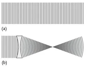
Considering an experiment using a focused beam more closely, we realize that there is always a certain tradeoff: Regardless of whether we consider small-angle scattering or high-angle diffraction, we will be working essentially in reciprocal space as a Fourier space. In the commonly used kinematic approximation, we implicitly assume that the sample is illuminated by a plane wave, but a focused beam is actually not a plane wave. The basic principle and the tradeoff is sketched in an idealized way in Figure 1.3. Focusing leads to a concentration of intensity in the focal spot, but always introduces an angular spread of the beam, coupled to the curvature of the wavefront. In practice, a beam of finite size never is a plane wave, but while the beam divergence delivered from synchrotron sources may in most cases be neglected, the convergence introduced after the lens is finite and not negligible. The result is that we loose resolution in reciprocal space compared to the unfocused beam, while direct space resolution is enhanced. This somehow sounds like a tradeoff with no net effect, but it is not; beam divergence can be increased up to a certain limit determined by the sample, that is, the peak width following from typical feature sizes, without loss of resolution there, while at the same time real-space resolution gets better. Nanoscience is a good field for these new X-ray probes: small structures inherently produce spread-out diffraction patterns, which allow considerable focusing without actually loosing information.
Figure 1.3 (a) Sketch of a parallel beam used in many experiments; wavefronts are plane, intensity is constant in space. (b) Focused beam; wavefronts are curved, and hence a certain angular spread is introduced; intensity is concentrated in the focal spot.
Nanoscience is at the same time a field often requiring to obtain very local information. Both technical as well as natural nanostructures obtain many properties from a particular, in most cases, rather inhomogeneous structure at the nanoscale, even if the macroscopic structure appears to be homogenous; which is often true for technological samples like alloys or ceramics, while biological specimen are more often inhomogeneous at almost any lengthscale – we already mentioned wood as a typical example. Hence, the combination of focused beams as probes and nanoscale specimen turns out to match very well in many cases.
Considering the prospects of these combinations, we may just consider some basic facts. Nanobeam developments have been around for roughly one decade. Focus diameters decreased from few micrometers down to the few 10 nm range, that is, by about two orders of magnitude. More and more beamlines have become available world wide, the main developments include two directions; many synchrotron centers go for rather long beamlines to get a better demagnification ratio. On the other hand, keeping a 100 nm diameter beam stable within few 10 nm or better over a distance of 100m is not trivial. Any vibration leads to an increase of the effective focus size (time-averaged), and there are a bunch of sources of vibration at large scale facilities, like vacuum pumps, air conditioning, heavy machinery, and so on. Vibration management is therefore an important part of further developments. But where, besides the principal tradeoff between real and reciprocal space resolution, are the limits? Compared to conventional optical microscopy it is rather clear that all angles remain comparatively small, that is, numerical apertures will not be approaching unity easily. Hence, the resolution limit will be one or two orders of magnitude away from the wavelength, that is, somewhere in the nm range. What can in principle be achieved depends, however, not only on the optics, the lens, but quite a lot also on other experimental restrictions.
As one example, we may consider a forward scattering or imaging experiment compared to a diffraction experiment. The former does not need a lot of sample alignment. In a very simplified way we may guess that one rotation to set the sample azimuth and two translations to bring the spot of interest into the X-ray focus will be enough. Consequently, the experiment can be rather compact, the focal length can be small and the demagnification accordingly large. The diffraction experiment, on the other hand, requires several rather precise rotation and translation stages to align at least the incidence angle of the beam with respect to the sample and the tilt of the sample perpendicular to the scattering plane, in addition to the sample azimuth and the translation stages. As a result, an optics with a larger “working distance”, that is, larger focal length, and hence a smaller demagnification, is required. Similar considerations apply for experiments where the sample needs to be kept in a particular environment, for instance to pursue in situ experiment during fabrication of nanostructures or during operation of nanodevices.
Very often, different demands for an experiment contradict each other. Absence of vibrations and the need...
Table of contents
- Cover
- Contents
- Related Titles
- Title Page
- Authors
- Copyright
- Foreword
- Preface
- 1 Introduction
- 2 X-ray Diffraction Principles
- 3 X-ray Focusing Elements Characterization
- 4 Scattering Experiments Using Nanobeams
- 5 Nanobeam Diffraction Setups
- 6 Spectroscopic Techniques Using Focused Beams
- 7 Coherent Diffraction: From Phase Sensitivity to Phase Retrieval
- 8 Lensless Microscopy Imaging: Context and Limits
- 9 Future Developments
- Abbreviation list
- References
- Index
Frequently asked questions
Yes, you can cancel anytime from the Subscription tab in your account settings on the Perlego website. Your subscription will stay active until the end of your current billing period. Learn how to cancel your subscription
No, books cannot be downloaded as external files, such as PDFs, for use outside of Perlego. However, you can download books within the Perlego app for offline reading on mobile or tablet. Learn how to download books offline
Perlego offers two plans: Essential and Complete
- Essential is ideal for learners and professionals who enjoy exploring a wide range of subjects. Access the Essential Library with 800,000+ trusted titles and best-sellers across business, personal growth, and the humanities. Includes unlimited reading time and Standard Read Aloud voice.
- Complete: Perfect for advanced learners and researchers needing full, unrestricted access. Unlock 1.5M+ books across hundreds of subjects, including academic and specialized titles. The Complete Plan also includes advanced features like Premium Read Aloud and Research Assistant.
We are an online textbook subscription service, where you can get access to an entire online library for less than the price of a single book per month. With over 1.5 million books across 990+ topics, we’ve got you covered! Learn about our mission
Look out for the read-aloud symbol on your next book to see if you can listen to it. The read-aloud tool reads text aloud for you, highlighting the text as it is being read. You can pause it, speed it up and slow it down. Learn more about Read Aloud
Yes! You can use the Perlego app on both iOS and Android devices to read anytime, anywhere — even offline. Perfect for commutes or when you’re on the go.
Please note we cannot support devices running on iOS 13 and Android 7 or earlier. Learn more about using the app
Please note we cannot support devices running on iOS 13 and Android 7 or earlier. Learn more about using the app
Yes, you can access Nanobeam X-Ray Scattering by Julian Stangl,Cristian Mocuta,Virginie Chamard,Dina Carbone in PDF and/or ePUB format, as well as other popular books in Technology & Engineering & Materials Science. We have over 1.5 million books available in our catalogue for you to explore.