![]()
Chapter 1
Millimeter-Wave Communication Systems
Wireless transmission with more than one Gigabit-per-second (Gbps) data rate is becoming essential due to increased connectivity between different devices. By 2020, the wireless network traffic will increase about 1,000 times as compared to that in 2015 [1]. The advanced technologies used in current high data rate wireless systems, such as Orthogonal Frequency Division Multiplexing (OFDM), Multiple-Input-Multiple-Output (MIMO), Quadrature Amplitude Modulation (e.g., 256-QAM, 1024-QAM) and carrier aggregation technique, help the systems in an existing frequency band achieve special efficiencies close to the theoretical limitation. Although individual user experience is improved, the system capacity remains basically unchanged. It is also harder to achieve a high data rate application below a 6-GHz band due to spectrum scarcity [1]. The MMW (30–300 GHz) band has drawn increasing interest over recent years for enabling such a highspeed wireless transmission because of the enormous raw bandwidth that is available, especially in a 60-GHz Industrial, Scientific and Medical (ISM) radio band. There is a 7-GHz unlicensed spectrum bandwidth available around 60 GHz. Several industrial standards have been released in that band, such as Wireless-HD, ECMA-387, IEEE 802.15.3c and IEEE 802.11ad/ay, etc. These standards focus on short-range indoor applications due to the intrinsic problem of signal propagation and the maximum allowed radiation power. However, the United States Federal Communications Commission (FCC) announced a change in the increase (from 40 to 82 dBm) of effective radiated power in the 60 GHz band in 2013 [2]. This change helps to overcome the limitation of signal propagation and extends the usage of 60 GHz for the outdoor long-distance communication system. This chapter will focus on the design implementation of a 60-GHz application system for outdoor environments. Specifically, it will cover the development of a System-on-Chip (SoC) RF transceiver with a Field Programmable Gate Array (FPGA) platform working as a baseband processor and Medium Access Control (MAC) layer.
1.1.System Structure
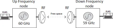
Figure 1.1 shows a 60-GHz communication system with two communication nodes. The two nodes operate on different frequencies with a 1-GHz carrier offset. The up- and down-band nodes work at 60 and 59 GHz, respectively. The local oscillator of these two nodes are different but they operate at the same time. That is how a full duplex can be achieved in this system. The user can access the system as a 1-kilometer Ethernet cable with a simple configuration.
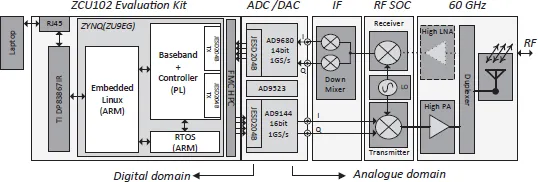
Figure 1.2 shows the detailed structure of one of the communication nodes. There are 5 sub-blocks in the node; namely, from left to right, a Xilinx Zynq evaluation kit, an Analog-to-Digital (ADC) and Digital-to-Analog (DAC) card, an Intermediate Frequency (IF) down mixer, a RF transceiver SoC, and a RF front-end device. The dark grey blocks are fixed modules, the light grey blocks are configurable modules and the white blocks are the fully customized modules. The modules in Figure 1.2 can be divided into two portions — digital domain on the left side and analog/RF domain on the right side.
The Zynq evaluation platform (ZC706/ZCU102) provides a Gigabit Ethernet interface for the users to access the platform through the RJ45 interface. The API software is provided for a laptop to access the platform through a standard TCP/IP protocol. An Embedded Linux system, which runs on the ARM core CPU, handles the data exchanges between the platform and an external computer. A Real-Time Operating System (RTOS), which runs on another ARM core CPU, handles the baseband control-related management tasks, such as timing management, data frame re-construction and error control. The digital baseband and part of the MAC are implemented in Programmable Logic (PL) using Verilog code. The main functions of the digital baseband design are signal modulation and demodulation, channel coding and decoding, and synchronization, as well as handling the data interface between the FPGA and ADC/DAC card through JESD204b.
Figure 1.1.A 60-GHz communication system.
Figure 1.2.Detail structure of the communication nodes.
For the RF transmitter, the Quadrature IQ signals from DAC will directly feed into the RF transceiver and are converted to a 60-GHz band directly. An external high-power amplifier is used to further increase the output power level to 15 dBm, as the output power of the RF transceiver SoC (around −5 dBm) is not enough for the target applications. Also, the two communication nodes in the system structure operate at a different frequency band with a 1-GHz carry offset. A duplexer is added after the PA to achieve full duplex operation by sharing a single antenna between transmitter and receiver signals. On the receiver side, an optional Low Noise Amplifier (LNA) can be used after the duplexer to provide a few dB of more gain if there are gaps between the estimation and measurement power level. The received signal after RF SoC is an IF signal with a 1-GHz carrier. A 1-GHz wideband IF down mixer is introduced to convert those signals back to the quadrature baseband signal. Then the Quadrature IQ signals are captured by the ADCs and sent to the baseband processor for further processing in the digital domain. The real-time controller in the receiver monitors the captured signal and responses to the transmitter immediately when there are uncorrectable errors or missing packages. The Quality of Service (QoS) software in the Real-Time Operating System will automatically turn the frame package length and modulation type to achieve the best trade-off between data rate and stability of the system.
1.2.60 GHz RF Signal Propagation Study
A reliable wireless system design requires a realistic channel model that closely resembles the real propagation environments. The channel represents a physical medium between the transmitter and receiver, and the channel model is the mathematical formula to describe the relationship between the input and output signal. There are many different types of interactions between electromagnetic waves and the environments which they propagate. The 60-GHz frequency band provides much more bandwidth than the spectrum used in existing wireless systems. However, it suffers from intrinsic problems such as poor propagation due to excess absorption or scattered signals by the atmosphere. The frequencies in 57–64 GHz is an oxygen absorption band that can experience an attenuation of about 15 dB/km, as the oxygen molecule (O2) absorbs electromagnetic energy. However, the higher transmitted power and antenna gain can possibly overcome the higher path loss in free space at a 60-GHz communication system.
1.2.1.Channel characteristic
This section summarizes some key channel characteristics of the 60-GHz channel. There are two types of channel characterization. The large-scale channel characterization consists of free space path loss and shadowing effect, while the small-scale channel characterization is usually caused by the multipath effect.
1.2.1.1.Large-scale channel characterization
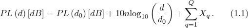
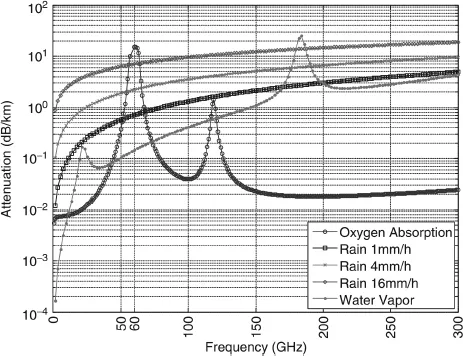
The path loss is defined as the ratio of received power to the transmitted power when the signal passes through the channel. A good path loss model is essential for link budget analysis and network planning. The 60 GHz signal that propagates at free space increases by approximately 22 dB, as compared to a 5-GHz band [3]. At the same time, the oxygen absorption and rain attenuation also significantly increase the path loss as shown in Figure 1.3. It is shown that oxygen introduces more than 10 dB/km of path loss around the 10-GHz band centered at 60GHz. This characteristic makes the 60-GHz system a suitable candidate for indoor rather than outdoors gigabit wireless communication applications. In general, the free space path loss can be expressed by Equation (1.1) below:
Figure 1.3.Free space oxygen absorption and rain attenuation across frequency[1].
Here PL(d0) will usually be given based on the measurement at the reference distance. For the Line-of-Sight (LoS) scenarios, it is sometimes deterministically calculated based on Equation (1.2) below:
where d0 and n denote the reference distance and path loss exponent, respectively. The λ in Equation (1.2) is the wavelength of a given frequency. Xq in Equation (1.1) accounts for additional attenuation due to specific obstruction by objects. The path loss exponent, n, for 60 GHz measurement ranges between 0.40 and 2.10 from various indoor environments for a LoS condition [3]. n can also be affected by the type of antenna used, the layout of the environment and the height of transmitter and receiver. Currently, most of the existing measurement work is related to an indoor environmental target for short distance applications [4]. Recently, there are a...