![]()
chapter i
MATERIALS AND PROCEDURES
Although we are dealing with freehand perspective in this book, it will be necessary—as explained in the introduction—to use some of the procedures of instrumental perspective in the development of our experiments. Hence, the student should be supplied with the following minimum items of equipment.
A drawing board about 16 by 24 inches is recommended. A piece of illustration board the same size, tacked to one side, will give a pleasanter surface on which to work; and when drawing on tracing paper, the white illustration board underneath will be especially appreciated.
Drawing paper 16 by 12 inches or thereabouts is recommended for many drawing exercises. Larger sheets will sometimes be necessary, as smaller drawings—particularly when instrumental work is involved —will not be so accurate. The smaller the drawing, the greater the probability of inaccuracy.
A T-square of good quality, and 45 and 30-60 degree triangles-all of the transparent type—are essential. Two brass-edged rulers, one 24 inches long, a draftsman’s compass and a pair of dividers will suffice as a minimum instrumental outfit.
When making instrumental diagrams, pencils with leads of hard degree are needed—H or 2H grades. These should be sharpened with a knife to points much longer than are produced by mechanical sharpeners. The leads should be kept well-pointed during all instrumental work, in order to avoid inaccuracies that would invalidate the whole procedure. For free sketching the softer leads will be preferred.
A large pad of tracing paper (about 19 by 24) is indispensable. Get samples from your dealer and select the most transparent sheet. There is a wide range of transparency in tracing papers. The student often will want to lay the transparent sheets over photographs and reproductions of artists’ work, in order to analyze them by tracing the converging lines and extending them until they find their vanishing points. In this way much will be learned, not only of natural appearances as recorded by the camera but of illustrators’ strategy in changing the rules to meet the needs of special situations. More about this later.
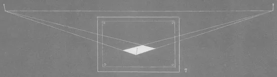
Many times, in making these analyses, it will be found necessary to fasten several sheets of paper together with scotch tape in order to secure a large enough area for the location of vanishing points which may be some distance away from the picture on either side. In this event, a yardstick may be substituted for the ruler in drawing the converging lines. When the vanishing points are found to be even beyond the edges of the drawing table, the drawing can be laid on the floor and the lines projected by means of strings or threads extending from pins stuck in the picture, as shown in fig. 7.
In such a case we might assume that the illustrator who made the original drawing established his far-flung points by the same method. However, the chances are that once he had established his vanishing points with strings from two converging lines on each side, he resorted to the following device to get directions of all other converging lines without actually carrying them out to the far-flung points.
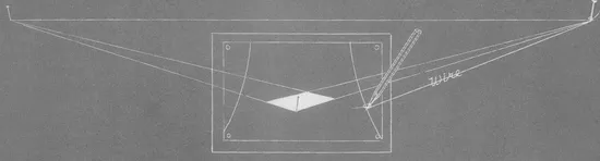
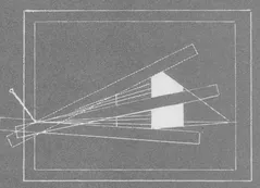
Extending a very thin wire—string is unsuited because it stretches—from pins stuck in at the vanishing points (already located, as in fig. 7) and attaching the other end to pencil points, arcs are inscribed on the drawing board as shown in fig. 8. (Good wire, as fine as thread, comes on spools.)
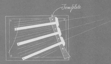
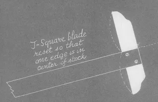
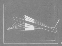
Templates are then cut with a sharp knife or razor blade, after having traced the arcs made on the drawing board and transferred them to thick cardboard. These templates are tacked firmly to the drawing board so that the arcs of their curved sides coincide with the arcs drawn by the wire compass demonstrated in fig. 8. Now the blade of a T-square placed against the curved side of a template (fig. 9) will always radiate from the vanishing point as it is moved along the arc; that is, its center line will. All one needs to do is to remove the blade—by removing the screws—and reset it on the stock so that one edge will be centered on the stock, as seen in fig. 10. Of course the blade must be set at exact right angles to the stock. By moving the T-square back and forth along the arcs, the direction of any line in the perspective drawing can be quickly and accurately drawn.
When a vanishing point is on the drawing board, a pin stuck upright at the vanishing point (as in fig. 11) will facilitate the drawing of converging lines. The straightedge can be placed against the pin and swung at any desired angle.
Fig. 12 demonstrates how strips of heavy cardboard, cut as shown, can be attached by pins to the vanishing points and used in place of the straightedge. Note that the pinhole in the strip must be in line with its drawing edge.
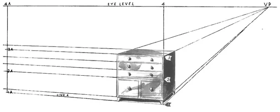
In fig. 13 we see another device for finding correct line directions when one or both of the vanishing points is beyond the edge of the drawing board. The right VP (vanishing point) is within range; the left VP is far out of bounds since the front lines of the cabinet are nearly horizontal.
We extend the vertical line of the nearest corner (1-3) upward to the eye-level (4). At any distance beyond the object at the left (the further the better) we drop a vertical from the eye-level to converging line (A)—whose direction has been determined freehand. This vertical (1A-4A) is shorter than the nearer vertical 1-4, but if it is divided proportionately into the same divisions as 1-4 we have points through which converging lines would pass on their way to their vanishing points far to the left. Thus the top of the cabinet (3) is half the height of 1-4. On the 1A-4A line we mark off a point (3A) halfway up that line. Point 2 on the cabinet is one-quarter the height; on 1A-4A we give 2A its corresponding position. Any number of measurements on 1-4 can be duplicated proportionately on 1A-4A.
A camera and a projection machine are indispensable tools in the contemporary illustrator’s equipment. Still more indispensable is such an inventive faculty as Frank J. Reilly brings to the solution of many of his illustration problems, of which the subject of this demonstration is an example—a picture of a marshalling yard, which ...