This book illustrates basic practical applications of optical principle. Working models of telescopes, microscopes, photographic lenses, and optical projection systems are diagrammed and explained in full, as are the basic experiments for determining accuracy, power, angular field of view, amount of aberration, and all other necessary facts about the instrument. Throughout the book, only elementary mathematics is used, for the benefit of the student and the beginner in the field of optics. The author, an assistant professor at the Imperial College of Science and Technology in London, shows how to set up working models of each of the four types of instruments named above, so that the reader can see for himself the effects of changing the focal length, using different types of lenses, rotating the lens, and other experiments. He also includes a number of experiments to illustrate theoretical principles such as the reflection and refraction of light and focal length measurements of concave and convex lenses. A chapter on the human eye follows, and the author explains how to set up a simple working model of the eye in order to illustrate myopia, astigmatism, hypermetropia, and the visual acuity of the eye. Professor Johnson concludes with an important chapter on the working and testing of optical glass, in which he describes the roughing of lenses, the principles of the grinding and polishing processes, abrasives, edging, angle measurement, and other important steps in the production of optical glass. An appendix is included on the cleaning of glass surfaces, silvering, photographic items, developers, collodion films, and waxes and cements used for various purposes in optical work. This is a valuable work for the student and the amateur hobbyist as well as for many who use optical instruments in science and industry. It is written clearly and economically, with the needs of the practical worker in the field of optics held constantly in mind.
Trusted by 375,005 students
Access to over 1.5 million titles for a fair monthly price.
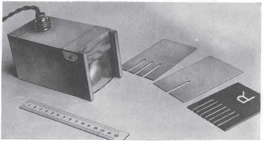
Some of the more introductory principles of reflection and refraction may be conveniently illustrated and verified by utilizing narrow beams of light sent out by a miniature projection lantern which can be moved about on a drawing board. Such a method whereby “ rays ” of light can be seen on the white paper being reflected to or from mirrors or through refracting systems, brings out the principles in vivid fashion; and a more lasting impression is made in the student’s mind than by doing such experiments by other methods.
FIG. 1.
Ray Projector for use on a Drawing Board.
The ray-projector, as it will be called, consists of a 12-volt, 36-watt, motor-car lamp bulb (with line filament) situated at the focus of a cylindrical lens rectangular in form (about
), with provision for interposing metal plates (having slots about
wide) in front of the lens, the whole being suitably housed in order to screen off stray light. The device is illustrated in Fig. 1, which will be found self-explanatory.
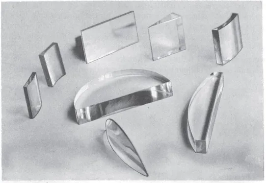
Fig. 2 shows some of the accessories which may be used with the ray-projector in order to carry out the experiments which follow.
Laws of Reflection.
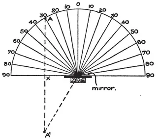
In order to prove experimentally that the angles of incidence and reflection are equal for rays meeting a reflecting surface, a method similar to that depicted in Fig. 3, may be employed. Draw a semi-circle of six inches radius and mark off intervals of ten-degree angles round a semi-circle of the circumference. Place a piece of plain mirror (preferably surface silvered) cemented to a wooden block along the diameter of the semi-circle with its face perpendicular to the drawing paper. Place the ray-projector round the circumference of the circle so that a narrow beam is projected along the 30 degree line; observe the angle at which the beam is reflected from the mirror, which should of course agree with the angle of incidence, namely, 30 degrees. Repeat the experiment for a number of different angles of incidence.
FIG. 2.
Accessories for carrying out “ Ray ” Experiments.
Angular Magnification by a Mirror.
Re-position the ray-projector so that the beam makes an angle of incidence and reflection of 30 degrees as before. Now rotate the mirror through 20 degrees until its face coincides with the line marked 70 on the left of the diagram. Find the new direction of the reflected ray.
Observe that the reflected ray moves through twice the angle moved by the mirror. In a sense this may be termed a form of magnification, inasmuch as the method facilitates the determination of small angular movements by doubling the effect through the medium of an attached mirror to the moving part; for example, in measuring the rotation of a galvanometer suspension.
Image in a Plane Mirror is same distance behind Mirror as Object is in Front.
Replace the silvered mirror by a piece of plane glass (supported at its end) along the line 90,90. Insert a pin at some such point as A.Looking into the plane glass mirror place a second pin at A′ so that the latter appears to coincide with A. Join AA′. Measure AX and A′X. Note that these distances are equal and that AA′ is perpendicular to the line 90,90.
FIG. 3
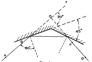
Reflection by two Mirrors Inclined at a Finite Angle.
A ray or beam of light reflected in two mirrors in succession will be deviated through an angle equal to twice the exterior angle between the mirrors.
Set up two mirrors perpendicular to the drawing paper, but with their edges adjacent to one another. (See Fig. 4.) Arrange them so that the angle between the mirrors is 135 degrees. Draw a line AB so that it makes an angle of incidence of 80 degrees with the normal to the first mirror. Direct the ray-projector so that a narrow beam travels along AB, and mark the direction CD on the paper as it emerges from the second mirror. Remove the mirrors, produce the line AB to P and produce CD until it intersects ABP in the point O.
FIG. 4.
Measure the angle POD with a protractor and compare it with the exterior angle between the two mirrors, namely, 45 degrees. The angle POD should be twice the latter.
Mirrors at 90 degrees.
Arrange the mirrors to be at right angles to one another, and direct a beam from the ray-projector so that it meets one of the mirrors at any angle of incidence. Note that the beam reflected from the second mirror is deviated through 180 degrees and returns parallel to the incidence beam. Observe that the reflected beam maintains a constant deviation, no matter at what angle the incident beam strikes the first mirror.
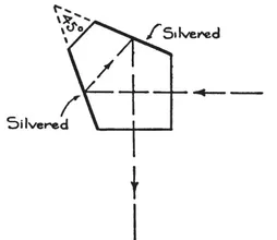
Mirrors at 45 degrees.
Arrange the two mirrors to be inclined at 45 degrees (i.e., exterior angle 135 degrees) and direct the ray-projector towards one of the mirrors. Note that the beam emerges from the second mirror after having been deviated through 270 degrees and therefore at right angles to the incident beam. Move the ray-projector round a little so that the beam strikes the first mirror at a different angle of incidence and observe that the deviation always remains constant. This illustrates the principle of the “ optical square ” as used in surveying, and the pentagonal prism as used in range-finders. If one of the latter prisms is available (see Fig. 5 and Fig. 10) this should be placed in the incident beam and rotated.
FIG. 5.
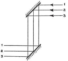
Reversals caused by Reflecting Systems.
Place a three slit diaphragm in front of the condenser of the ray-projector instead of the single slit and then arrange two mirrors as indicated in Fig. 6. Mark on the paper the incident rays 1, 2 and 3, and observe that they emerge from the second mirror un-reversed. The simple periscope and the sextant are examples of the instruments which utilize this principle.
FIG. 6.
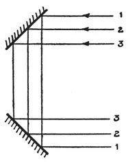
FIG. 7.
Binocular Prism.
Place the second mirror so that it opposes the first. (See Fig. 7.) Note that in the plane of the paper the rays are reversed.
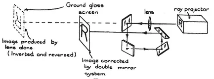
If instead of the three slit diaphragm a transparent letter R mounted on an opaque background be placed in front of the condenser of the ray-projector and a four inch focus lens arranged so as to produce an image of the letter R on a ground glass screen mounted on the drawing paper, it will be found possible to observe reversals “ up and down ” as well as “ right and left.”
FIG. 8.
In this connection, by mounting two other mirrors, as in Fig. 8, on wooden supports and placing t...
Table of contents
Title Page
Copyright Page
FOREWORD TO DOVER EDITION
Table of Contents
CHAPTER I - REFLECTION AND REFRACTION OF LIGHT
CHAPTER II - FOCAL LENGTH MEASUREMENTS
CHAPTER III - THE EYE
CHAPTER IV - THE TELESCOPE
CHAPTER V - THE MICROSCOPE
CHAPTER VI - PHOTOGRAPHIC LENSES
CHAPTER VII - OPTICAL PROJECTION SYSTEMS.
CHAPTER VIII - OPTICAL GLASS: ITS WORKING AND TESTING.
APPENDIX
INDEX
A CATALOG OF SELECTED DOVER BOOKS IN SCIENCE AND MATHEMATICS
Frequently asked questions
Yes, you can cancel anytime from the Subscription tab in your account settings on the Perlego website. Your subscription will stay active until the end of your current billing period. Learn how to cancel your subscription
No, books cannot be downloaded as external files, such as PDFs, for use outside of Perlego. However, you can download books within the Perlego app for offline reading on mobile or tablet. Learn how to download books offline
Perlego offers two plans: Essential and Complete
Essential is ideal for learners and professionals who enjoy exploring a wide range of subjects. Access the Essential Library with 800,000+ trusted titles and best-sellers across business, personal growth, and the humanities. Includes unlimited reading time and Standard Read Aloud voice.
Complete: Perfect for advanced learners and researchers needing full, unrestricted access. Unlock 1.5M+ books across hundreds of subjects, including academic and specialized titles. The Complete Plan also includes advanced features like Premium Read Aloud and Research Assistant.
Both plans are available with monthly, semester, or annual billing cycles.
We are an online textbook subscription service, where you can get access to an entire online library for less than the price of a single book per month. With over 1.5 million books across 990+ topics, we’ve got you covered! Learn about our mission
Look out for the read-aloud symbol on your next book to see if you can listen to it. The read-aloud tool reads text aloud for you, highlighting the text as it is being read. You can pause it, speed it up and slow it down. Learn more about Read Aloud
Yes! You can use the Perlego app on both iOS and Android devices to read anytime, anywhere — even offline. Perfect for commutes or when you’re on the go. Please note we cannot support devices running on iOS 13 and Android 7 or earlier. Learn more about using the app
Yes, you can access Optics and Optical Instruments by B. K. Johnson in PDF and/or ePUB format, as well as other popular books in Physical Sciences & Optics & Light. We have over 1.5 million books available in our catalogue for you to explore.