![]()
CHAPTER 1
Facts and Facts Controllers
1.1 INTRODUCTION
Since the past three decades, the construction of both generation facilities and, in particular, new transmission lines has been delayed due to energy cost, environmental concerns, right-of-way restrictions, and other legislative and cost problems. Recently, the philosophy of open access transmission has facilitated the development of competitive electric energy markets. New economic, social, and legislative developments have demanded a review of traditional power transmission theory and practice and the creation of new concepts to allow full utilization of existing power generation and transmission facilities, without compromising system availability and security. In the late 1980s, the Electric Power Research Institute (EPRI), Palo Alto, California, USA formulated the vision of flexible AC transmission system (FACTS) in which various power electronics-based static controllers enhance controllability and increase power transfer capability while maintaining sufficient steady-state and transient margins [1, 2, 3, 4, 5, 6]. The main objectives of FACTS technology are to increase the usable transmission capacity of lines and control power flow over designated transmission corridors.
The FACTS controllers achieve these objectives by controlling the interrelated parameters that govern the operation of transmission systems including series impedance, shunt impedance, current, voltage, phase angle and the damping of power system oscillations. The normal power transfer over the transmission lines can be estimated to increase significantly by using FACTS controllers (about 50%, according to some studies conducted) [4].
The development of FACTS controllers has followed two distinctly different technical approaches, both resulting in a comprehensive group of controllers able to address targeted transmission problems. The first group employs reactive impedances or a tap changing transformer with thyristor switches (i.e., having no intrinsic turn-off ability) as controlled elements. Examples include the static VAr compensator (SVC), the thyristor-controlled series capacitor, and the phase shifter. The second group uses self-commutated static converters as controlled voltage sources. Examples include the static compensator (STATCOM), the static synchronous series compensator (SSSC), unified power flow controller (UPFC), the interline power flow controller (IPFC), and the generalized unified power flow controller (GUPFC) [1, 2, 3, 4, 5, 6].
Now, compared to the thyristor-based FACTS devices, the voltage-sourced converter (VSC)-based FACTS controllers generally provide superior performance characteristics and uniform applicability for transmission voltage, effective line impedance, and angle control. They also offer the unique potential to exchange real power directly with the AC system, in addition to providing the independently controllable reactive power compensation [1,3]. Consequently, these controllers are evoking a lot of interest from both the industry and the academia worldwide.
Among the VSC-based FACTS controllers, the STATCOM is the earliest device to be conceived. It operates as a shunt-connected static VAr compensator whose capacitive or inductive output current can be controlled independent of the AC system voltage [7, 8, 9, 10]. The first STATCOM, with a rating of ±100 MVAR, was commissioned in late 1995 at the Sullivan substation of the Tennessee Valley Authority (TVA) in the United States, jointly sponsored by the EPRI and the TVA and manufactured by the Westinghouse Electric Corporation [11,12]. The STATCOM is described in Section 1.2.
1.2 THE STATCOM
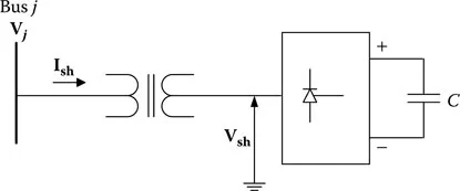
As already discussed in Section 1.1, the STATCOM is a VSC-based shunt FACTS controller. It is primarily used for voltage control of buses. The schematic diagram of a STATCOM is shown in Figure 1.1.
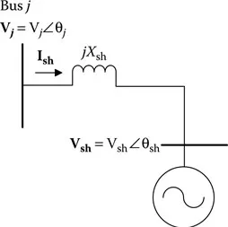
From the figure, it can be observed that the STATCOM is connected to any bus j of a power system through a step-up transformer, also known as the coupling transformer. For power system analysis, we will focus on fundamental frequency, positive sequence voltages and currents of the STATCOM. The (fundamental frequency, positive sequence) output voltage of the STATCOM is shown as Vsh. The STATCOM draws a current Ish from the system. For ease of analysis, we will neglect the losses in the coupling transformer and the STATCOM. Also, the STATCOM rating limits are ignored. The equivalent circuit of Figure 1.1 is shown in Figure 1.2.
FIGURE 1.1 A STATCOM connected to any bus j of an n-bus power system.
FIGURE 1.2 Equivalent circuit of Figure 1.1.
From the figure, using Kirchhoff's voltage law (KVL), we can write Vj = Vsh + jIsh Xsh, where Xsh represents the leakage reactance of the coupling transformer. Now, the STATCOM output voltage Vsh is controllable in both its magnitude and its phase. Since we have assumed a lossless STATCOM (and also due to the fact that the STATCOM cannot generate active power by itself), the phase angle of Vsh is kept equal to that of Vj. This can be explained as follows. From Figure 1.2, for a lossless STATCOM, the active power transfer from bus j to the STATCOM will be
This implies θsh = θj. Thus, in the phasor diagram, Vsh and Vj will be collinear phasors, having only two possibilities, depending upon whether the magnitude of Vsh is made more or less than Vj. These two cases correspond to the two phasor diagrams shown in Figure 1.3a and b. In the first case ...