- 568 pages
- English
- ePUB (mobile friendly)
- Available on iOS & Android
eBook - ePub
Mechanical Design and Manufacture of Hydraulic Machinery
About this book
This volume in the Hydraulic Machinery Book Series covers the most important types of hydraulic machinery: hydraulic turbines for transforming water power to mechanical output; and pumps for producing fluid pressure for many purposes. It describes the features of mechanical design of various types of turbines and pumps. The structure of a hydraulic machine is decided primarily to satisfy the need of fluid flow, so hydraulic characteristics of the machines are also stressed. Manufacturing processes of turbines and pumps and their requirements are referred to in chapters on mechanical construction.
Trusted by 375,005 students
Access to over 1.5 million titles for a fair monthly price.
Study more efficiently using our study tools.
Information
Chapter 1
General Concepts of Hydraulic Turbine Construction
R.K. Turton
1.1 Hydroelectric Generating Unit Layouts
Hydroelectric stations may be classified into high, medium and low head categories, so that it is possible to class the types of machines involved by referring to head and flow as shown in Figure 1.1. Figure 1.2 illustrates the types of runner used: from the impulse (Pelton) turbine for high head; the Francis turbine for medium/low head; and the axial-flow (Kaplan) turbine for low head installations.
High head and most medium head units are driven by water accumulated in dams through long tunnels and penstocks, and some medium and low head machines are placed in dam power houses or run-of-river stations which form part of barrages in rivers and estuaries. A further way of classification is by power output, with generating units of large outputs of 100MW or more, medium-size units of 25 to 75MW, and small or micro hydroelectric stations of limited outputs.
1.2 Typical Construction of Turbines
1.2.1 Impulse turbines
These machines may be of either vertical or horizontal shaft design, with the pressure head converted into high velocity jets by specially designed nozzles. The jets impinge on a runner provided with buckets as shown in Figure 1.3. The head of a recent installation, for example, is 1200m and the generated output is 260MH, which is typical of the latest high specific output schemes.
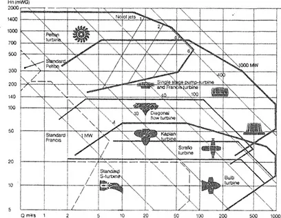
Figures 1.1 Typical ranges of application for turbines
(Drawing courtesy Sulzer Escher Wyss)
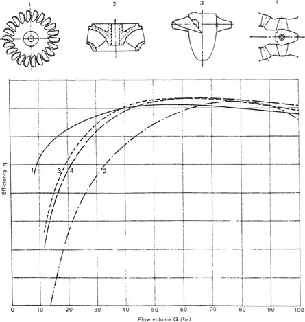
Figure 1.2 Comparison of efficiency characteristics of different types of turbines
(Drawing courtesy Sulzer Escher Wyss)
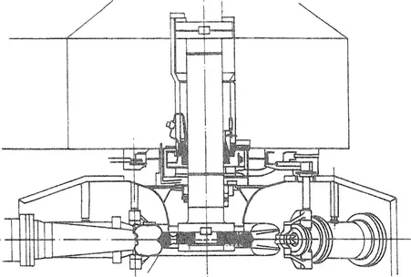
Figure 1.3 Typical vertical shaft multi-jet Pelton turbine
(Drawing courtesy Sulzer Escher Wyss)
Small Pelton turbines may be installed where there is enough head, and units of 100kW or more are in operation. Many hydroelectric power stations use small Pelton turbines for station stand-by power.
1.2.2 Francis turbines
Figure 1.4 illustrates a large Francis turbine layout, the spiral case directs water through guide vanes (wicket gates) into the runner and out through the draft tube to the tail water. The turbine shown is a medium head machine that generates 715MW under 113m head. A Francis turbine is a mixed-flow machine, the characteristic shape of the runner varies with head and specific speed, as shown in Figure 1.5.
1.2.3 Axial-flow turbines
An axial-flow turbine may have fixed runner blades or variable-pitch blades, the former is commonly called a propeller turbine and the latter a Kaplan turbine. Figure 1.6 shows a typical Kaplan turbine layout. This machine with an output of 103MW under a head of 24.4m has a runner diameter of 8.4m. This turbine is typical of low head axial-flow machines and has a spiral case of near rectangular shape and stay vanes made up of separate columns.
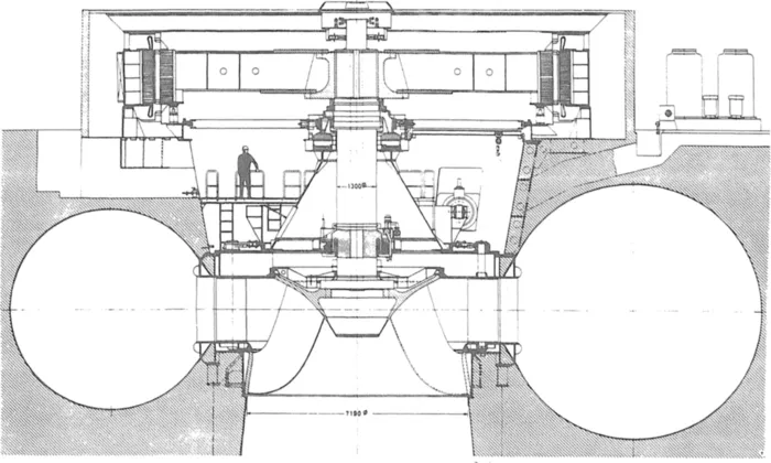
Figure 1.4 Large capacity medium head Francis turbine
(Drawing courtesy J.M. Voith)
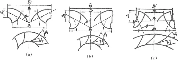
Figure 1.5 Characteristic profile of Francis runners
(a) Low specific speed (b) Medium specific speed (c) High specific speed
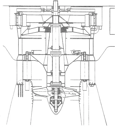
Figure 1.6 Typical Kaplan turbine with rectangular spiral case made of concrete
(Drawing courtesy Escher Wyss)
A variation used in small, river barrage and estuary installations is the bulb turbine. Here water flows around the generator bulb, through the guide vanes which are set in a mixed-flow annulus section and into the axial-flow runner. The entire unit is effectively tubular in shape as there is no spiral case, hence it is also called a tubular turbine. The bulb turbine shown in Figure 1.7 has an output of 25MW under a 7m head, a runner diameter of 7.7m and a rotational speed of 62min−1.
1.2.4 Pump-turbines
Early pumped storage power stations used a four machine layout, with a turbine and generator as one set and a pump and motor as a second set. The turbine generates at high grid demand times, and the pump uses surplus power from the grid at non-peak demand times, to refill the supply reservoir for the turbine. Later the two electrical machines were combined into one to form a generator-motor with the turbine and pump connected one on each end of it. The aggregate is called a tandem set, or a three machine layout.
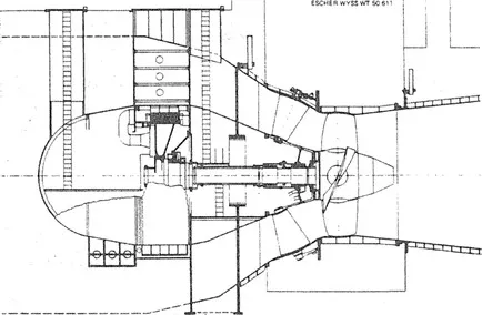
Figure 1.7 Cross-section of a large bulb turbine
(Drawing courtesy Sulzer Escher Wyss)
Present-day pumped storage power stations use a reversible pump-turbine which rotates in one direction as a pump and in the other direction as a turbine. A pump-turbine closely resembles a Francis turbine, as shown in Figure 1.8, but all components of the flow passage are designed to work...
Table of contents
- Cover
- Half Title
- Title Page
- Copyright Page
- Contents
- Preface
- Foreword of the Editor
- Acknowledgements
- Contributor
- 1 General Concepts of Hydraulic Turbine Construction
- 2 Construction of Francis Turbines
- 3 Construction of Axial—Flow and Diagonal—Flow Turbines
- 4 Construction of Tubular Turbines
- 5 Construction of Impulse Turbines
- 6 Construction of Pump—Turbines
- 7 Inlet Valves and Discharge Valves
- 8 Structural Design of Hydraulic Turbines
- 9 Manufacture of Hydraulic Turbines
- 10 Construction of Small Turbines
- 11 General Concepts of Pump Construction
- 12 Construction of Centrifugal Pumps
- 13 Construction of Axial—Plow, Mixed—Flow and Tubular Pumps
- 14 Material Selection for Pump Construction
- 15 Manufacturing Processes of Pumps
- 16 Pump Drives
- Appendxi I Nomenclature of symbols
- Appendxi II Reference list of organisations
- Appendxi III Reference list of educational establishments
Frequently asked questions
Yes, you can cancel anytime from the Subscription tab in your account settings on the Perlego website. Your subscription will stay active until the end of your current billing period. Learn how to cancel your subscription
No, books cannot be downloaded as external files, such as PDFs, for use outside of Perlego. However, you can download books within the Perlego app for offline reading on mobile or tablet. Learn how to download books offline
Perlego offers two plans: Essential and Complete
- Essential is ideal for learners and professionals who enjoy exploring a wide range of subjects. Access the Essential Library with 800,000+ trusted titles and best-sellers across business, personal growth, and the humanities. Includes unlimited reading time and Standard Read Aloud voice.
- Complete: Perfect for advanced learners and researchers needing full, unrestricted access. Unlock 1.5M+ books across hundreds of subjects, including academic and specialized titles. The Complete Plan also includes advanced features like Premium Read Aloud and Research Assistant.
We are an online textbook subscription service, where you can get access to an entire online library for less than the price of a single book per month. With over 1.5 million books across 990+ topics, we’ve got you covered! Learn about our mission
Look out for the read-aloud symbol on your next book to see if you can listen to it. The read-aloud tool reads text aloud for you, highlighting the text as it is being read. You can pause it, speed it up and slow it down. Learn more about Read Aloud
Yes! You can use the Perlego app on both iOS and Android devices to read anytime, anywhere — even offline. Perfect for commutes or when you’re on the go.
Please note we cannot support devices running on iOS 13 and Android 7 or earlier. Learn more about using the app
Please note we cannot support devices running on iOS 13 and Android 7 or earlier. Learn more about using the app
Yes, you can access Mechanical Design and Manufacture of Hydraulic Machinery by Mei Zu-yan in PDF and/or ePUB format, as well as other popular books in Business & Materials Science. We have over 1.5 million books available in our catalogue for you to explore.