- English
- ePUB (mobile friendly)
- Available on iOS & Android
eBook - ePub
Anchorage in Concrete Construction
About this book
A comprehensive treatment of current fastening technology using inserts (anchor channels, headed stud), anchors (metal expansion anchor, undercut anchor, bonded anchor, concrete screw and plastic anchor) as well as power actuated fasteners in concrete. It describes in detail the fastening elements as well as their effects and load-bearing capacities in cracked and non-cracked concrete. It further focuses on corrosion behaviour, fire resistance and characteristics with earthquakes and shocks. It finishes off with the design of fastenings according to the European Technical Approval Guideline (ETAG 001), the Final Draft of the CEN Technical Specification 'Design of fastenings for use in concrete' and the American Standards ACI 318-05, Appendix D and ACI 349-01, Appendix B.
Trusted by 375,005 students
Access to over 1 million titles for a fair monthly price.
Study more efficiently using our study tools.
Information
1
Introduction
1.1 A historical review
The task of connecting building components is as old as building itself. Throughout history, the job has been handled in different ways depending on the building material, the structural system and the particular requirements of the construction.
In wood construction traditional joinery began with timbers bound with tough natural fibres and developed into various types of interlocking, screwed and doweled joints, glued and finger joints as well as embedded steel plates and ring connectors.
Steel construction, a comparatively ‘young’ discipline, employs connection techniques ranging from cast-iron fittings to rivets, bolts and welding, whereby only bolting and welding are in common use today.
In concrete and masonry construction, various means of anchoring are in regular use (Fig. 1.1).
Fig. 1.1 Fastening methods in concrete
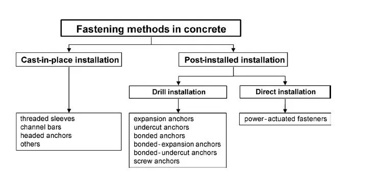
The mortar used in masonry assemblies can be regarded as the oldest type of connection material. In fact, the hewn dovetails, cast metal joints and embedded metal studs or sleeves historically employed in stone masonry may be considered to be the predecessors of today’s modern fastening technology. Today, these methods have been largely replaced by plastic and/or metal elements of sophisticated design inserted into pre-drilled holes and secured via friction, mechanical interlock, chemical bond, or a combination thereof. Today there are systems available that are suitable for practically any type of masonry.
Concrete and reinforced concrete construction initially borrowed fastening techniques from other building trades, either unchanged or only slightly modified. Wood lathe placed in the formwork was anchored in the concrete via pre-driven nails and served as an attachment point for the entire range of building systems, as well as for suspended ceilings. Later, threaded sleeves, anchor channels and headed studs welded to steel plates were employed, these being secured inside the formwork and cast into the concrete
These so-called “cast-in-place” techniques were later rivalled by systems designed to be installed after the concrete had cured. The evolution of drilling technology from chisels to rotary-percussion tools and the more recent development of diamond core drilling has opened up new opportunities for the field of post-installed anchoring technology.
For minor loads, the ubiquitous plastic anchor, successor to hemp and lead plugs, has all but replaced other techniques. To cope with higher loads, various types of metal expansion anchors have been developed that employ, in principle, the same functional principles but with varying construction details and attendant variations in installation and application conditions.
Bonded anchors, in which a steel rod is grouted into a pre-drilled hole, continue to be frequently used. Representing the latest stages in this chain of development are undercut anchors, hybrid systems employing bond, friction and/or mechanical interlock, and second-generation self-tapping screws.
Parallel with the development of anchors for pre-drilled holes, the technology of high-strength steel nails or studs driven into steel and concrete by an explosive or pneumatic energy source (so-called power-actuated fastening) has seen growing use over the past four decades. These systems serve to simplify the attachment of piping systems, lightweight suspended ceilings, etc., and are also widely employed for the attachment of metal deck to steel framing.
Clearly, post-installed fastening in concrete and masonry is a relatively young discipline, meaning that the state of the art is generally in a state of flux. Consequently, these systems typically cannot be regulated via prescriptive standards, as is done, say, with high-strength structural bolts. Consequently, in the member states of the European Community, the U.S. and other countries the design and installation of post-installed fastenings is usually carried out in accordance with product-specific approvals.
1.2 Requirements for fastenings
Fastenings must be designed in such a way that they do the job for which they are intended, are durable and robust, and exhibit sufficient load-carrying and deformation capacity. Fastenings for less critical applications, e.g. securing lightweight duct, lighting, and wiring, can be selected on the basis of the user’s experience and do not usually require analysis or structural review (outside areas of seismic hazard). On the other hand, fastenings that are relevant to life safety, i.e. whose failure could pose a hazard to life or result in significant economic loss, must generally be selected on the basis of structural considerations and are typically designed and detailed by a structural engineer. The design establishes whether the requirements of the serviceability and ultimate limit states are met. The serviceability limit state includes requirements for limiting deformation, and requirements on durability (corrosion, chemical resistance). At the ultimate limit state it must be proven that the design value of the actions does not exceed the design value of the fastening resistance. Analyses of the serviceability and ultimate limit states generally make a distinction between the type and direction of the load. Section 1.3 deals with loads acting on connections and section 3.7 with the distribution of these loads to the fasteners. The capacities of the fastenings are explained in relation to the type of fastener and type of base material as well as failure mode in sections 4 to 9. The behaviour of fasteners under seismic excitations and under fire is dealt with in sections 10 and 11 respectively. Corrosion and corrosion protection is discussed in section 12 and the influence of fastenings on the capacity of concrete members in which they are installed is explained in section 13. Requirements on the suitability of fasteners for the application in question and the design of fastenings are discussed in section 14.
1.3 Nature and direction of actions
Actions (loads) can be classified according to the frequency of their occurrence and their duration. In addition, we can make a distinction as to whether or not inertial forces are involved. Table 1.1 provides an overview of various actions. Dynamic forces arise in cases of impact, earthquake, explosion or machines that generate large inertial loads. If the load is permanent or occurs only a few times and does not include inertial forces, then the action is considered to be static. If the number of load cycles is large but, again, inertial loads are not present, then we refer to fatigue loading. If inertial forces are involved, then the action is dynamic, regardless of the number of load cycles.
Table 1.1 Classification of actions
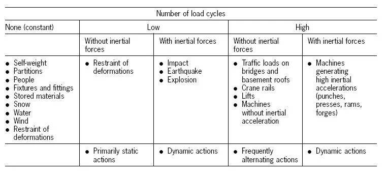
Static actions are the sum of permanent and semi-permanent (slowly changing) actions. These actions are sometimes referred to as dead and live loads. The permanent actions result from the weight of the structural components to be anchored and any other constant loads that the attached components must carry, e.g. backfill, floor coverings, and plaster. Semi-permanent actions include, for example, foot traffic, fixtures and fittings, non-load-bearing lightweight partitions, stored materials, wind and snow. Given values for the applicable permanent and semi-permanent actions can be found in the relevant national and international standards (e. g. DIN 1055, Eurocode 1: EN 1990: 2002 (2002), ASCE 7 (American Society of Civil Engineers (2002)) .
Deformations can occur in anchored components, e.g. due to temperature fluctuations or due to shrinkage and creep of the concrete components. Temperature fluctuations may be due to weather conditions, as with building facades, or may simply be a result of the component function, as in the case of chimneys, silos, boiler rooms and cold storage rooms. Restraint of these deformations gives rise to stresses in the fasteners, the magnitude of which depends on the geometry and position of the fastenings as well as the mechanical properties of the materials involved. These stresses may be relevant to the fatigue-resistance of the fastener, depending on the number of temperature-induced strain cycles. For example, in the case of facade support structures, assumptions of 104 to 2 · 104 load cycles are often used in design.
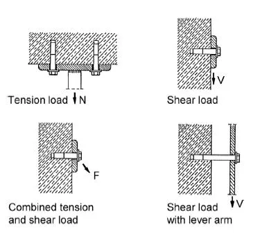
Fig. 1.2 Actions on fasteners
Frequently alternating actions (fatigue loads) are caused by, for example, traffic loads, crane rails, lift and machines. The magnitude of the changing action required for design is again to be found in the relevant national and international standards. These standards also define whether a changing action should be viewed as a static action or as a fatigue load. For example, a wind load frequently changes in magnitude and direction but is often regarded as a static load for design purposes.
The essential difference between dynamic and static actions lies in the presence of inertial and attenuation forces. These forces arise from the induced accelerations and must be taken into account when determining the forces on the fastening. Dynamic forces are brought about by earthquakes, sudden actions such as impacts and explosions, and by machines with high inertial acceleration, e.g. printing presses. Dynamic actions generated by machines are also regarded as relevant for fatigue.
Loads can occur as tension, shear or a combination of tension and shear. In the case of shear, we distinguish between loading with or without bending of the fastener (Fig. 1.2).
2
Fastening systems
2.1 General
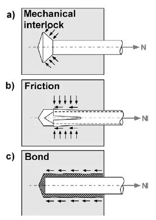
Fasteners transfer applied tension loads to the base material in various ways. Load-transfer mechanisms are typically identified as mechanical interlock, friction or bond (Fig. 2.1).
Mechanical interlock involves transfer of load by means of a bearing interlock between the fastener and the base material. Mechanical interlock is the load-transfer mechanism employed by headed anchors, anchor channels, screw anchors, and undercut anchors.
Friction is the load-transfer mechanism employed by expansion anchors. During the installation process, an expansion force is generated which gives rise to a friction force between the anchor and the sides of the drilled hole. This friction force is in equilibrium with the external tensile force.
In the case of chemical interlock, the tension load is transferred to the base material by means of bond, i.e. some combination of adhesion and micro-keying. Chemical interlock is the load-transfer mechanism employed by bonded anchors.
Fig. 2.1 Anchor load-transfer mechanisms
The majority of commercially available fasteners resist tension loads via one or more of the above described mechanisms.
Another way of differentiating anchor systems is by the way they are installed. A distinction is made between cast-in-place, drilled-in and direct installation. Cast-in-place components are secured in the formwork prior to casting. Drilled-in anchors are installed in holes drilled into the hardened base material. Direct installation refers to studs or nails driven into the base material with powder cartridges or pneumatic action.
The following sections describe anchors commonly used in plain and reinforced concrete.
2.2 Cast-in-place systems
A variety of inserts are used for cast-in-place installations. These include lifting inserts for the transportation of precast concrete components, anchor channels, embedded plates with headed studs, bent reinforcing bars equipped with internally threaded unions, as well as custom components for hanging heavy facade panels and for securing masonry. Sections 2.2.1 to 2.2.4 describe the more common cast-in-place systems listed above. Design procedures for cast-in-place headed anchors and anchor channels are outlined in section 14.
As previously discussed, cast-in-place systems transfer external tension loads into the base material by means of a mechanical interlock between the embedded component and the concrete. Their positions must be coordinated with the reinforcement layout. They can also be installed in heavily reinforced elements without difficulty. The advantage of cast-in-place systems lies in the fact that the location of the anticipated external loads is known and so can be accommodated in the design of the reinforced concrete member through appropriately placed reinforcement. The disadvantage lies in the extra layout and planning required for these systems, as well as in the potential for erroneous placement.
2.2.1 Lifting inserts
Lifting inserts used for the transport of plain and reinforced concrete precast elements must often conform to applicable local specifications regulating their design. Examples include the safety guidelines of Germany’s Hauptverband der gewerblichen Berufsgenossenschaften (1992) and the U. S. Occupational Safety and Health Administration (OSHA) (1989) which specifies capacity requirements for inserts and lifting hardware.
In the case of cast-in cable loops, the crane hook or lifting tackle is simply attached to a loop of cable projecting from the concrete (Fig. 2.2).
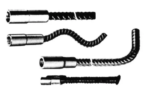
A wide variety of commercially available lifting inserts are equipped with flush-set internally threaded sleeves to accommodate lifting tackle (Fig. 2.3). These are anchored in the concrete by various means including deformations, transverse dowels, and hairpins. Lifting inserts may also be constructed by swaging an internally threaded insert directly onto the end of a piece of reinforcing bar (Fig. 2.4).
Fig. 2.2 Cast-in cable loop for crane hook (Bertram (1997))
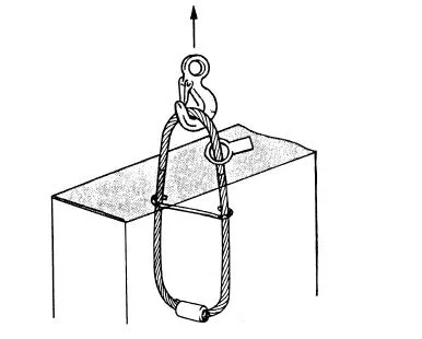
Fig. 2.3 Typical threaded sleeves (Bertram (1997))
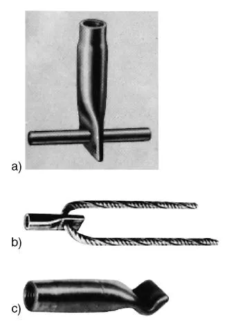
Fig. 2.4 Transport anchors with swaged threaded sleeves (Bertram (1997))
A simple form of transport anchor is constructed from bar stock, one end of which has been sheared and bent to form a ‘swallow tail’. A hole drilled into the opposite end serves to accommodate the lifting hardware attachment (Fig. 2.5).
Headed anchors with cold-formed heads (Fig. 2.6) at each end are designed to accommodate special lifting hardware that engages the larger head.
There are also systems available in which the lifting tackle can be remotely disconnected (Fig. 2.7).
The installation instructions of the manufacturer must be adhered to when using lifting inserts. These specify permissible load, minimum concrete strength, minimum component thickness, minimum spacing, and edge distance, as well as the necessary reinforcement. As a rule, specific additional reinforcement is required since lifting inserts are often positioned close to edges or in narrow components.
Fig. 2.5 Steel flatbar with “...
Table of contents
- Cover
- Preface
- 1: Introduction
- 2: Fastening systems
- 3: Principles
- 4: Behaviour of headed studs, undercut anchors and metal expansion anchors in non-cracked and cracked concrete
- 5: Behaviour of cast-in anchor channels in non-cracked and cracked concrete
- 6: Behaviour of bonded anchors in non-cracked and cracked concrete
- 7: Behaviour of plastic anchors in non-cracked and cracked concrete
- 8: Behaviour of power actuated fasteners in non-cracked and cracked concrete
- 9: Behaviour of screw anchors in non-cracked and cracked concrete
- 10: Behaviour of anchors under seismic loading
- 11: Behaviour of anchors in fire
- 12: Corrosion of anchors
- 13: Influence of fastenings on the capacity of components in which they are installed
- 14: Design of fastenings
- References
- Index
Frequently asked questions
Yes, you can cancel anytime from the Subscription tab in your account settings on the Perlego website. Your subscription will stay active until the end of your current billing period. Learn how to cancel your subscription
No, books cannot be downloaded as external files, such as PDFs, for use outside of Perlego. However, you can download books within the Perlego app for offline reading on mobile or tablet. Learn how to download books offline
Perlego offers two plans: Essential and Complete
- Essential is ideal for learners and professionals who enjoy exploring a wide range of subjects. Access the Essential Library with 800,000+ trusted titles and best-sellers across business, personal growth, and the humanities. Includes unlimited reading time and Standard Read Aloud voice.
- Complete: Perfect for advanced learners and researchers needing full, unrestricted access. Unlock 1.4M+ books across hundreds of subjects, including academic and specialized titles. The Complete Plan also includes advanced features like Premium Read Aloud and Research Assistant.
We are an online textbook subscription service, where you can get access to an entire online library for less than the price of a single book per month. With over 1 million books across 990+ topics, we’ve got you covered! Learn about our mission
Look out for the read-aloud symbol on your next book to see if you can listen to it. The read-aloud tool reads text aloud for you, highlighting the text as it is being read. You can pause it, speed it up and slow it down. Learn more about Read Aloud
Yes! You can use the Perlego app on both iOS and Android devices to read anytime, anywhere — even offline. Perfect for commutes or when you’re on the go.
Please note we cannot support devices running on iOS 13 and Android 7 or earlier. Learn more about using the app
Please note we cannot support devices running on iOS 13 and Android 7 or earlier. Learn more about using the app
Yes, you can access Anchorage in Concrete Construction by Rolf Eligehausen,Rainer Mallée,John F. Silva in PDF and/or ePUB format, as well as other popular books in Technology & Engineering & Civil Engineering. We have over one million books available in our catalogue for you to explore.