Physics is very much an experimental science, but too often, students at the undergraduate level are not exposed to the reality of experimental physics ― i.e., what was done in a given experiment, why it was done, the background of physics against which the experiment was carried out and the changes in theory and knowledge that resulted. In this hook, the author helps to remedy the situation by presenting a variety of "landmark" experiments that have brought about significant alterations in our ideas about some aspect of nature. Among these scientific milestones are discoveries about the wave nature of x-rays, isotopes, the meaning of atomic number, superconductivity, fine structure in the spectrum of helium, the transistor, the neutrino, the maser and laser, higher symmetry for elementary particles and other seminal discoveries.
Over 120 illustrations enhance the text, often reproductions of those published with the original experimental results. The result is a fascinating survey ideal as a supplement for intermediate or advanced undergraduate courses in experimental physics, history of science, radio and radar astronomy, crystallography, high energy physics and other disciplines.
- 336 pages
- English
- ePUB (mobile friendly)
- Available on iOS & Android
eBook - ePub
Landmark Experiments in Twentieth-Century Physics
About this book
Trusted by 375,005 students
Access to over 1.5 million titles for a fair monthly price.
Study more efficiently using our study tools.
Information
Chapter 1
The Wave Nature of X Rays
Scarcely any other invention in history was exploited as promptly as were x rays. Within a few months of their discovery by Wilhelm Röntgen in 1895, they were being used for medical diagnostic purposes and for the examination of metal castings. Yet it was not until nearly twenty years later that their true nature was established.
The question of the nature of x rays had been widely argued almost from the start. Many scientific observers, as well as a large part of the general public, appeared to regard them as identical to cathode rays, the beams of electrons emitted from the cathode of an electrical discharge in a low-pressure gas, despite the fact that they were unaffected by magnetic fields. Other scientists thought that they were longitudinal vibrations in the “aether”; still others suspected that they were transverse waves of a character similar to light. The difficulty lay in the fact that the known properties and producible effects did not seem to fit any of these hypotheses. When the rays struck matter, they were scattered, much as light is scattered from a cloudy liquid. But they could not be refracted or reflected.1 Efforts to produce polarization by selective absorption, in the manner used for visible light in tourmaline, were also unsuccessful. Charles Barkla, in 1906, demonstrated polarization by double scattering,2 but many people were not convinced, since such experiments could also be explained in terms of spinning particles. The real touchstone of the wave nature, as Thomas Young had recognized in regard to visible light a century earlier, was the production of interference effects. Attempts in this direction were hampered by a lack of knowledge of the wavelength range. The decisive work was done in 1912 by Max von Laue, Walter Friedrich, and Paul Knipping, and earned a Nobel prize in physics for Laue in 1914. This chapter describes their work, as originally presented to the Royal Bavarian Academy of Sciences and published in its Meeting Reports, and subsequently republished in Annalen der Physih.
Actually, previous efforts to detect interference had been made. As early as 1899, Hermann Haga and Cornelis Wind had passed a beam of x rays through a triangular aperture. If the x rays were waves, they should have been diffracted by the edges of the slit, and the image on a photographic plate some distance behind the slit should have been broader than the slit itself3; the amount of broadening, together with the dimensions of the apparatus, would then give an estimate of the wavelength. Haga and Wind concluded that if there were interference effects, the wavelengths involved must be less than about 10-9 cm. This work was repeated by Bernhard Walter and Robert Pohl in 1908, with even more discouraging results—they put limits of the order of 10-10 cm on the wavelength. Their work, however, was reanalyzed in 1912 by Arnold Sommerfeld, with the help of photometric measurements on the original photoplates by Peter Koch, and the conclusion of Haga and Wind was supported: No assurance could be found that waves were actually involved, but if they were, they must have wavelengths of the order of 10-9 cm.
What Laue did was to fit this piece of data with others from the theory of solids and atomic theory. He knew, first, that “already in 1850 there was introduced into crystallography by Bravais the theory that the atoms in crystals are arranged in a spatial lattice. If the Röntgen rays truly consist of electromagnetic waves, then it is to be expected that on excitation of the atoms to vibrations, free or forced, the space-lattice structure will give rise to interference phenomena.” Moreover, “the constants of this lattice can be easily calculated from the molecular weight of the crystallized compound, its density, and the number of molecules per gram molecule, in addition to the crystallographic data. One finds for them just the order of magnitude 10-8 cm....” This was just what was needed to produce significant interference phenomena with x rays, if indeed the rays were wavelike in character.
The known results of optical interference theory could not be taken over directly, because of the “considerable complication ... that for the space lattice a threefold periodicity is present, whereas for optical gratings one has a periodic repetition only in one direction, or ... at most two directions.” Laue, therefore, worked out the theory on the basis that each atom was excited an equal amount by the influence of an incident plane wave traveling at the speed of light. The details of this derivation are of no concern here; the crucial result was a set of three equations for the direction in which the scattered intensity would have a maximum. Each of these equations “represents a set of circular cones whose axes coincide with one of the edges” of the elementary unit of the space lattice. “Now, obviously, only in exceptional cases will it happen that one direction satisfies all three conditions at the same time.... Nevertheless, a visible maximum of intensity is to be expected when the line of intersection of two cones of the first two sets lies close to a cone of the third set.” If the scattered rays strike plane photographic plates, these maxima will produce isolated spots, which, however, should be grouped along families of conic sections4—more particularly, at points where three curves, one from each of three families, intersect or nearly intersect.
“It must be observed that for a given space lattice the division into elementary parallelepipeds is not unique, but can be carried out in innumerable ways.... According to the foregoing, the intensity maxima must be able to be grouped along interrupted conic sections around ... axes [arising from such alternative divisions], as in general, to each such kind of division belongs a way of grouping the maxima.”
At Laue’s suggestion, Friedrich and Knipping carried out the experimental test. “After some preliminary studies with a provisional apparatus,” the apparatus shown in Fig. 1-1 was built. “From the Röntgen rays proceeding from the anticathode A of a Röntgen tube, a small pencil of about 1 mm diameter was cut off by the stops B1 to B4. This pencil penetrates the crystal Kr, which is set up on a goniometer G. Around the crystal, in various directions and at different distances, were fixed photographic plates P, on which was recorded the intensity distribution of the secondary radiation emanating from the crystal. The setup was guarded against unwanted radiation in a satisfactory way by a large lead shield S as well as by the lead case K.
“The arrangement of the entire experimental setup was effected by optical means. We had a cathetometer, whose telescope was fitted with a crosshair, set up immovably. The ‘hot spot’ of the anticathode, the stops, and the goniometer axis were brought in turn into the optical axis of the telescope.... The stops B1 to B3 mainly blocked off the secondary radiation from the tube walls, while stop B4 formed the limits for the pencil of Röntgen rays incident on the crystal. This ordinarily had a diameter 0.75 mm, was drilled in a lead disk 10 mm thick, and could be adjusted by means of three positioning screws (not shown) in such a way that the axis of the hole coincided exactly with the axis of the telescope or the axis of the pencil of rays. In this way it was arranged that a ray pencil of circular cross section fell on the crystal.... The tube R served ... to avoid as much as possible the secondary rays that were produced by the primary radiation striking the rear wall of the case.
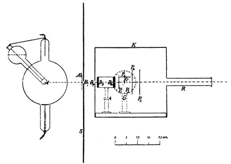
Fig. 1-1. Friedrich and Knipping’s apparatus for studying the scattering of x rays penetrating a crystal. [Ann. Physik 41 (1912), p. 979, Fig. 1.]
“After this adjustment, ... the axis of the goniometer was set perpendicular to the path of the rays in the usual way. In the same way the different plate holders were ... adjusted.... When the apparatus was oriented to that extent, the crystal to be irradiated, which was fastened to the goniometer table by a trace of sticky wax, was put in place, this again with the help of the telescope already mentioned.... This ... very essential adjustment we could make to within a precision of a minute [of arc].”
The first exposure with the final apparatus used a “middling” crystal of copper sulfate that had been used in the preliminary studies. The figures obtained on plates P4 and P5 in this exposure are shown in Fig. 1-2. “It is noteworthy that the distances (crystal—P4) and (crystal—P5) are in proportion to the sizes of the figures on P4 and P5, respectively, from which it is established that the rays travel out from the crystal in straight lines. It is further to be observed that the sizes of the individual secondary spots, despite the greater distance of plate P5 from the crystal, remain the same. This is taken as a sure indication that the secondary rays producing each individual spot leave the crystal as a parallel beam.
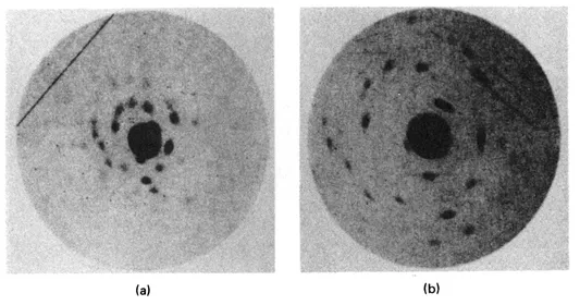
Fig. 1-2. Two figures obtained in the first exposure: (a) from plate P4 of Fig. 1-1, (b) from plate P5. [Ann. Physik 41 (1912), Plate I, Figs. 2 and 1, respectively.]
“It is to be expected that the phenomenon will be more transparent and easy to understand with a crystal of the regular [i.e., cubic] system than with the triclinic copper sulfate, since it can be assumed5 with certainty that the pertinent space lattice is of the greatest possible simplicity. Regular zinc blende seemed suitable to us.... We had a plane parallel plate of 10 X 10 mm dimensions and 0.5 mm thick cut ... parallel to a cube face (perpendicular to a crystallographic principal axis) from a good crystal. This plate was oriented ... so that the primary rays penetrated the crystal perpendicular to the cube face. Figure [1-3] shows the result of one such trial. The pattern of the secondary spots is completely symmetric around the position of the unscattered beam.... [The fourfold nature of the symmetry] is certainly one of the most beautiful pieces of evidence for the space lattice of the crystal, and that no property other than the space lattice alone comes into play here.”
A slightly later paper by Laue contained a more detailed analysis. Laue had, as noted earlier, already derived the equations for the directions of the maxima. For the case of a cubic crystal with the incident beam directed along one of the principal axes, they take the simple form

(1-1)
where λ is the wavelength; α is the length of one edge of the elementary cubic unit of the crystal lattice; α, β, and γ are the cosines of the angles between the direction of the maximum and the x, y, and z axes, respectively (the z axis being the direction of the incident beam); and h1, h2, and h3 are integers (positive, negative, or zero). He was able to account for all the points in Fig. 1-3 by suitable choices of the three h’s and the assumption that the radiation consisted of five discrete wavelengths.
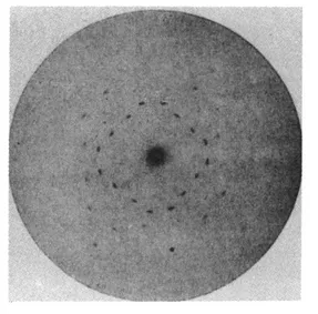
Fig. 1-3. The pattern of spots produced by x rays after passing through a crystal of zinc sulfide. [Ann. Physik 41 (1912), Plate II, Fig. 5.]
Laue’s analysis was soon subjected to criticism by W. L. Bragg, who noted that there were several sets of h’s which would satisfy the ...
Table of contents
- Title Page
- Copyright Page
- Table of Contents
- Dedication
- Preface
- Acknowledgments
- Chapter 1 - The Wave Nature of X Rays
- Chapter 2 - Isotopes
- Chapter 3 - The Meaning of Atomic Number
- Chapter 4 - Superconductivity
- Chapter 5 - The Strange Behavior of Liquid Helium
- Chapter 6 - Precision Values for Nuclear Magnetic Moments
- Chapter 7 - Fine Structure in the Spectrum of Hydrogen
- Chapter 8 - The Magnetic Moment of the Electron
- Chapter 9 - The Transistor
- Chapter 10 - Disproof of a Conservation Law
- Chapter 11 - Recoilless Emission and Absorption of Radiation
- Chapter 12 - Reality of the Neutrino
- Chapter 13 - The Maser and the Laser
- Chapter 14 - “Tunneling” and Superconductivity
- Chapter 15 - Higher Symmetry for Elementary Particles
- Chapter 16 - A Possible Cosmological Clue
- Appendix A - Historical Background and Sketch of the BCS Theory
- Name Index
- Subject Index
Frequently asked questions
Yes, you can cancel anytime from the Subscription tab in your account settings on the Perlego website. Your subscription will stay active until the end of your current billing period. Learn how to cancel your subscription
No, books cannot be downloaded as external files, such as PDFs, for use outside of Perlego. However, you can download books within the Perlego app for offline reading on mobile or tablet. Learn how to download books offline
Perlego offers two plans: Essential and Complete
- Essential is ideal for learners and professionals who enjoy exploring a wide range of subjects. Access the Essential Library with 800,000+ trusted titles and best-sellers across business, personal growth, and the humanities. Includes unlimited reading time and Standard Read Aloud voice.
- Complete: Perfect for advanced learners and researchers needing full, unrestricted access. Unlock 1.5M+ books across hundreds of subjects, including academic and specialized titles. The Complete Plan also includes advanced features like Premium Read Aloud and Research Assistant.
We are an online textbook subscription service, where you can get access to an entire online library for less than the price of a single book per month. With over 1.5 million books across 990+ topics, we’ve got you covered! Learn about our mission
Look out for the read-aloud symbol on your next book to see if you can listen to it. The read-aloud tool reads text aloud for you, highlighting the text as it is being read. You can pause it, speed it up and slow it down. Learn more about Read Aloud
Yes! You can use the Perlego app on both iOS and Android devices to read anytime, anywhere — even offline. Perfect for commutes or when you’re on the go.
Please note we cannot support devices running on iOS 13 and Android 7 or earlier. Learn more about using the app
Please note we cannot support devices running on iOS 13 and Android 7 or earlier. Learn more about using the app
Yes, you can access Landmark Experiments in Twentieth-Century Physics by George L. Trigg in PDF and/or ePUB format, as well as other popular books in History & Science History. We have over 1.5 million books available in our catalogue for you to explore.