![]()
1
Introduction
1.1 DEFINITION
The term voltammetry is applied to that group of electroanalytical techniques in which the current (ampere) that flows through an electrochemical cell is measured as the potential (volt) applied to the electrodes in the cell is varied. The term, first used by Kolthoff in 1940 [1], is derived from the units of the electrical parameters measured—volt-am (pere)-metry. It is important at this point to distinguish between the terms voltammetry spelt with ‘mm’ and voltametry spelt with only one ‘m’. The term voltametry has been used to describe the technique generally known as ‘controlled current potentiometric titration’.
The essential difference between voltammetric and other potentiodynamic techniques, such as constant current coulometry, is that in voltammetry an electrode with a small surface area (< 10–5 m2) is used to monitor the current produced by the species in solution reacting at this electrode in response to the potential applied to it. Because the electrode used in voltammetry is so small, the amount of material reacting at the electrode can be ignored. This is in contrast to the case in coulometry where large area electrodes are used so that all of a species in the cell may be oxidised or reduced.
When mercury, flowing through a fine capillary so that it emerges as droplets, is used as the small electrode in a voltammetric cell the technique has the special name polarography. This name is derived from the fact that the electrode can be polarised. An electrode is said to be polarised when no direct current flows across its interface with the solution even though there is a potential difference across this interface. In his definitive work published in 1922 [2] on ‘Electrolysis with a dropping mercury electrode’, Jaroslav Heyrovsky referred to this phenomenon and called the recorded current-potential polarisation curves polarograms.
The recommendation of IUPAC [3] is that voltammetry is the general term to be used when current potential relationships are being investigated and that only when a flowing conducting liquid electrode (such as a dropping mercury electrode) is used as the working electrode should the term polarography be used. Polarography, the original technique, is thus a special case of voltammetry.
1.2 THE CELL
The electrochemical cell used in voltammetry is a multi-phase system in which electrical energy is used to bring about a chemical change (electrolysis) in species in the cell. In its simplest form, such a cell consists of two electronic conductors called electrodes immersed in an electrolytic conductor (ionic solution) containing the substance of analytical interest called the analyte. This ionic solution completes the electrical circuit. It is the processes which occur at the solution-electrode interface involving the analyte and the factors that influence these interfacial processes that are exploited in electro-analytical chemistry. The application of a voltage or a current from an external source to the electrodes produces an electrical response from the analyte in the cell solution. The nature and magnitude of this response may be used to both identify and quantify the analyte.
The small electrode used to monitor the response of the analyte is known as the working electrode (WE). Even though only a negligible amount of material is involved in the processes occurring at the working electrode, its small size ensures that a high current density develops at its surface. Consequently, it is the processes which occur at this small electrode that control the current flow through the cell.
The small current-controlling WE may be constructed from a wide variety of conducting materials. The more common materials used include various forms of graphite and metals such as mercury, gold or platinum. These electrodes may be stationary, rotating or, in the case of mercury, flowing with respect to the cell solution. They are usually named after the material from which they are made and in some cases after other physical characteristics. For example, the dropping mercury electrode or DME; the mercury thin film electrode or MTFE; the hanging mercury drop electrode or HMDE; the glassy carbon electrode or GCE; the carbon paste electrode or CPE; the rotating platinum electrode or RPE; a chemically modified electrode or CME; and so on.
The second electrode in the simple cell, called a counter electrode (CE), serves two purposes. It is used to control the potential applied to the working electrode and to complete the circuit for carrying the current generated by the processes occurring at the WE. In the former role it must act as a reference electrode (RE). The ideal reference electrode must be a completely depolarisable electrode, i.e. it must be able to maintain a constant potential at its interface with the cell solution irrespective of any current that may flow across this interface. This can only be achieved if the reaction that controls the potential of this electrode is very fast and if there are no significant changes in the ion concentration profile in the vicinity of the interface—conditions that cannot be realised in practice unless the current that flows through the cell is extremely small and the composition of the cell solution does not change significantly from sample to sample. In the simple two-electrode cell the counter electrode must be much larger in area than the working electrode so that (i) the current density at its surface is so small that the electrode processes occurring at the CE do not affect the current signal generated at the WE in any significant way, and (ii) the flow of current through the cell as a result of the processes at the small WE has a minimal effect on the concentration profile at the CE surface so that its function as a reference electrode is not seriously impaired.
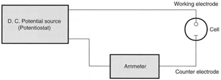
A simple arrangement for measuring the current that flows through a two-electrode cell as the voltage applied to the electrodes is varied is shown in Figure 1.1. Accurate measurements are only possible with this basic set-up when no voltage drop occurs in the cell and, as indicated above, the counter electrode is maintained in a constant-composition solution. The solution in the cell will have a resistance to the flow of current and as a consequence there will be a potential drop across the cell due to the current flow generated by the electrode process. Although this may be minimised by adding a high concentration of a supporting electrolyte (SE) to the cell solution it can never be eliminated. The voltage applied to the cell, Vapp, then is given by:
where | EWE and Eref are the potential drops across the working electrode-solution interface and reference electrode-solution interface, respectively, when the reactions at both electrodes are written as reductions. icell is the current flowing through the cell. When the analyte is reduced electrons flow from the WE to the analyte and the current is called a cathodic current. When the analyte is oxidised the electron flow is reversed and the current is called an anodic current. R is the cell resistance in ohms. |
Figure 1.1 Two-electrode arrangement for measuring current-potential curves.
Since the absolute values of single electrode potentials cannot be measured, it is normal to refer all working electrode potentials to that of the reference electrode so that equation 1.1a becomes:
where | E’WE is the potential of the working electrode relative to the reference electrode being used. |
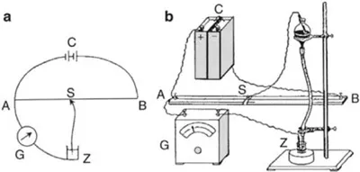
It is only under zero current conditions when no reaction is occurring at the working electrode that the voltage applied to the two-electrode cell is identical with the sum of the potential drops at the electrode interfaces. Since in a real measurement situation a current flows through the cell and V differs from the sum of the two electrode potentials by icell R—the so-called ‘iR drop’—it is preferable to refer to the plot of icell against Vapp obtained from a two-electrode cell as a current-voltage curve. A very simple experimental arrangement for the two-electrode system is to use the mercury collecting in the bottom of the cell as the counter electrode (i.e. a mercury pool electrode or MPE). However, as the cell solution composition varies so will the potential of the MPE. For more precise control of EWE it is necessary to use as a reference electrode an electrode that can maintain a more constant potential than the mercury pool electrode.
Figure 1.2 (a) Schematic arrangement for electrolysis with the dropping mercury electrode, (b) A simple practical apparatus [4].
In modern measuring systems the current carrying role of the counter electrode is separated from its potential control role by introducing a third electrode, the auxiliary electrode, AE, to the cell to complete the current carrying circuit. The area of this auxiliary electrode must be large compared to that of the working electrode for the reason (i) given above. The addition of the auxiliary electrode means that the counter electrode now is used only to control the potential of the working electrode and so becomes a true reference electrode. Since no current flows through the poten...