1
Coronary and Perfusion Imaging with Cardiovascular Magnetic Resonance: Current State of the Art
Amedeo Chiribiri, Markus Henningsson, Claudia Prieto, Michael Jerosch-Herold and Rene M. Botnar
CONTENTS
1.1 Introduction
1.2 Technical Challenges and General Imaging Strategies for Coronary CMR
1.2.1 Compensation of Cardiac Motion: ECG Triggering
1.2.2 Compensation of Respiratory Motion: Navigator
1.2.3 Coronary Artery Imaging
1.2.3.1 Sequences
1.2.3.2 Contrast-Enhancing Spin Preparations
1.2.3.3 Contrast Agents
1.2.3.4 Recent Improvements in Acquisition Speed and Resolution
1.2.4 Coronary Vein Imaging
1.2.5 Coronary Vessel Wall Imaging
1.2.6 Special Considerations: Intracoronary Stents
1.3 Clinical Applications
1.3.1 Coronary Artery Angiography for the Detection of CAD
1.3.2 Coronary Anomalies and Aneurysms
1.3.3 Coronary Bypass Grafts
1.3.4 Coronary Vessel Wall Imaging
1.3.5 Coronary Vein Imaging
1.4 Myocardial Perfusion Imaging
1.4.1 Techniques for Magnetic Resonance Myocardial Perfusion Imaging
1.4.2 Clinical Applications
1.5 Conclusions—Future Perspective
References
1.1 Introduction
Despite substantial improvements in prevention and treatment,1 coronary artery disease (CAD) remains the leading cause of death and disability in the Western world.2 The current gold standard for the diagnosis of CAD is cardiac catheterization. In the United States alone, 16,300,000 patients are suffering from CAD, and approximately 1,000,000 cardiac catheterizations are performed each year.2 In up to 40% of examined patients, no significant coronary artery stenoses are diagnosed.3 Therefore, a noninvasive test that could directly assess the integrity of the coronary lumen would be desirable.4 Cardiovascular magnetic resonance (CMR) allows a comprehensive evaluation of myocardial function, perfusion, and morphology in patients with CAD.5 In addition, magnetic resonance angiography (MRA) can be used for direct visualization of the coronary artery lumen, whereas black blood techniques allow for visualization of the coronary vessel wall,6 making CMR a tool capable of providing all required diagnostic information in one single examination.
Moreover, the same MRA techniques allow the visualization of the coronary veins anatomy, which is of interest for the optimal placement of pacemaker leads in cardiac resynchronization therapy.7,8
This chapter provides an update on current improvements in coronary MRA as well as an overview on its current clinical usage.
1.2 Technical Challenges and General Imaging Strategies for Coronary CMR
Coronary MRA demands dedicated techniques to optimize image contrast and to ensure a high signal-to-noise ratio (SNR), yielding a clear delineation from blood-filled structures or the vessel walls with high spatial resolution. Since high spatial resolution is required for adequate visualization of the coronary vessels, the concomitant intrinsic cardiac and respiratory motions pose a major challenge to coronary MRA and vessel wall imaging.
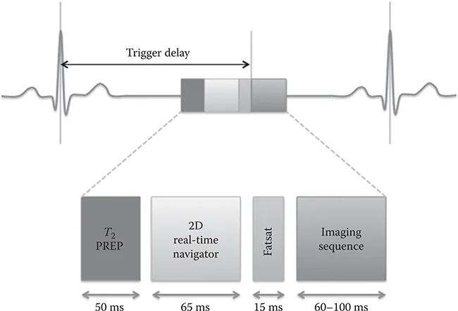
To overcome this, a standard coronary MRA protocol comprises (1) electrocardiogram (ECG) triggering for synchronization of the heart motion with the data acquisition, (2) respiratory navigation for synchronization/ compensation of the respiratory motion, (3) the imaging sequence itself, and (4) prepulses for spin preparation to ensure sufficient image contrast (Figure 1.1).
1.2.1 Compensation of Cardiac Motion: ECG Triggering
To freeze cardiac motion, data acquisition has to be synchronized with the cardiac cycle and be limited to periods of minimal cardiac movement.9 Resting periods occur in end-systole (approximately 280–350 ms after the R wave) and in mid-diastole (immediately prior to atrial systole). Both acquisition strategies (systolic or diastolic) have advantages and disadvantages (Table 1.1).
The optimal trigger delay and the length of the acquisition window depends on the patients’ heart rate, on the type of imaging sequence used, on the structure to visualize (arteries versus veins), and other hemodynamic factors. While the use of a heart-rate dependent formula to identify the mid-diastolic resting period is effective in many subjects, there may be considerable intersubject variation.10 Therefore, the resting period should be identified for each patient from a free-breathing high temporal resolution cine scan in the four-chamber view performed shortly before the coronary scan.9 Real-time arrhythmia rejection to exclude irregular heartbeats may further improve coronary MRA image quality.11–14
Another important parameter to consider is the duration of the resting period. It is typically longer for the left compared to the right coronary artery system. Thus, the length of the acquisition window of a whole heart acquisition is determined by the duration of RCA diastasis.
1.2.2 Compensation of Respiratory Motion: Navigator
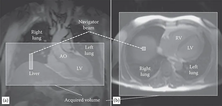
The displacement of the heart due to respiration can exceed 2–3 cm, requiring synchronization of image acquisition with the respiratory cycle. High-resolution three-dimensional (3D) datasets are not compatible with breath-hold acquisitions. Several approaches have been tested to reduce the effect of respiratory motion on image quality. Prospective real-time navigator gating and correction techniques are the current approach to minimize respiratory motion artifacts.15,16 A pencil beam one-dimensional navigator typically positioned on the dome of the right hemidiaphragm is used to monitor the foot head motion17 of the diaphragm immediately prior to coronary image acquisition (Figure 1.2). Depending on the position of the diaphragm, the data is either accepted, when the position falls within a certain acceptance window (usually 3–5 mm), or rejected. In the latter case, the data has to be remeasured in the subsequent cardiac cycle. Reduction of the acceptance window reduces the motion artifacts but increases the overall acquisition time because more data is rejected. An acceptance window of 5 mm usually allows an efficiency approaching 50%.18–20
FIGURE 1.1
Schematic representation of pulse sequence elements for MRA. Image acquisition is performed in mid-diastole after a trigger delay from the R wave of the ECG. The imaging block is preceded by a contrast-enhancing spin preparation (T2 PREP), a 2D selective real-time navigator pulse for respiratory motion compensation, and a frequency-selective fat-suppression prepulse (FATSAT). These sequence blocks are repeated with every heart cycle. (Adapted from Botnar, R.M. et al., Circulation, 99, 3139–3148, 1999. With permission.)
TABLE 1.1
Comparison between Systolic and Diastolic Coronary CMR
Diastolic Resting Period | Systolic Resting Period |
Advantages Longer acquisition window (~100–125 ms/heartbeat) Higher blood flow (higher signal in gradient echo sequences) | Advantages Less sensitive to heart rate variability Larger diameter of the venous vessels |
Disadvantage Higher sensitivity to heart rate variability | Disadvantage Shorter acquisition window (~50 ms/heartbeat) |
To increase the percentage of accepted data, the position of the imaging slice can be prospectively adapted to the measured respiratory position. Normally the movement of the heart due to breathing is less pronounced than the motion of the diaphragm itself, and a scale factor between 0.4 and 0.6 has been used for optimal slice tracking. However, also with the use of these techniques, respiratory induced motion of the heart often cannot be completely modeled by a simple translation along the foot–head direction, and it has been shown that in up to 30% of patients, an affine transformation models the respiratory motion more accurately.21,22
Other proposed approaches include the use of image-based navigators that directly track cardiac motion, navigators that monitor the movement of the epicardial fat,23 scanning in prone position,24,25 and the use of an abdominal or a thoracic banding.25,26
1.2.3 Coronary Artery Imaging
1.2.3.1 Sequences
3D approaches require long acquisition times and were initially not feasible. The first approaches to coronary artery angiography were attempted by Edelman22 and Manning27 by two-dimensional (2D) gradient-echo techniques. One slice was acquired in 16 heartbeats (in a single breath-hold) and patients were free to breathe between acquisitions. The introduction of navigator techniques allowed the acquisition of data in free breathing and 3D techniques became feasible.
FIGURE 1.2
Planning of the navigator and of the whole heart imaging volume from coronal (a) and axial (b) scout images. A pencil beam one-dimensional navigator is posit...