Continuing development in technology has raised the dependence on electrical power availability. Commercial power resources enable the modern world to operate even with all the required demands. The electric power system has a significant role in several applications including the storage, transfer, and use of electric power. The electric power system is an electrical network of components organized to convert one form of energy into a useful form of electrical power. The operation and performance of electrical equipment is mainly based on the quality of power supply. With the emergence of sophisticated technology, intelligent technology demands power that is free of disturbance and interruption.
The mismatch between power generation and load disturbance affects generating voltage and frequency of the standalone system. In order to overcome this concern, a power-generating unit becomes an essential part of regulating the frequency of the system, tie-line power flow between connected areas, voltage value, and load flow conditions within the desired value. Nonetheless, nowadays, the electric energy demand is rapidly increasing due to the enormous development in technology. Consequently, large-scale power systems are created to balance energy demand with generation. When load demand is increased in any one of the power systems, the remaining connected areas share the power between them to maintain the system in stable condition. The size and complexity of systems are increasing with large interconnections of control areas. The complexity of systems is reduced with the help of recently developed modern control theory.
The power balance among the generating power and the total load demand provides good quality power and reliable power supply to all consumers. During the nominal loading conditions, each power-generating unit takes care of its stability and operating point. Whenever sudden load disturbance occurs in any of the generating units, it disturbs the frequency of the system and tie-line power flow within the interconnected power systems. In addition, the tie-line power flow deviations between the interconnected power plant and damping oscillations that occur in the system response affect the stability of the power system. In order to guarantee power system stability, a speed governor can be used to act as a primary control loop; in addition, a secondary controller can also be introduced to retain the system parameters within the quantified value. The frequency regulation and active power control is called load frequency control (LFC). Furthermore, the voltage control and reactive power are referred to as automatic voltage regulation (AVR). The main aim of LFC is to preserve the frequency with a constant value even with the continuous change of the active power demand, which is related to the loads, and it regulates the tie-line power exchange between the interconnected areas.
The electrical grid of interconnected networks is used to deliver the electrical supply from the generating unit to power consumers. The grid contains power-generating stations to generate the electrical power supply. The high voltage transmission line carries the generated power from the sources to load centers, where the distribution centers connect individual customers and where the power-generating stations are positioned near the fuel source.
1.1Load Frequency Control and Automatic Generation Control
The automatic generation control (AGC) as well as the LFC play the foremost role in the power system process and the control of any type of power plant unit. For generating and power delivery, suitable analysis of the power supply quality and regularity become essential during emergency situations. In this situation, power-generating units are interconnected via tie-lines to obtain good quality of power supply. The interconnected power system comprises hydro, nuclear, wind, solar, gas, and thermal power plants. Thus, the system response yields damping oscillations in the frequency and tie-line power flow deviations during the load demand condition. To deliver good quality power supply to consumers, the secondary controller gain values should change uniformly. During the higher-load demand condition, controller gain values change maximally and this repeating process maintains the quality of generated power by keeping error values equal to zero.
Typically, the PID controller consists of three basic terms: proportional controller (P), integral controller (I), and derivative controller (D). The proportional controller reduces the peak overshoot in the system responses, the integral controller reduces the steady-state error to zero, and the stability of the system is increased by using the derivative controller. The input of PID controller is the area control error (ACE) and the output of the controller is the control signal (delPref). The output of controller is given into the power system as a reference signal.
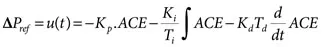
The PID controller design in the literature review included several methods for optimization of controller gain values with different cost functions. Such functions include the integral square error (ISE), integral time square error (ITSE), integral absolute error (IAE), and integral time absolute error (ITAE) cost functions. In this book, the PID controller is considered a feedback controller, which gives the appropriate control signal for controlling the power plant during abnormal conditions. The value of the control signal generated by the controller for each area is given in the following expression:
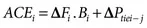
ΔPref, or u(t), represents the control signal generated by the controller. In addition, Kp, Ki, and Kd represent the proportional, integral, and derivative controller gain values, respectively. ACE indicates the area control error. Based on the IEEE standards, ACE is defined as linear combinations of change in frequency and tie-line power flow deviations between connected areas. So, proper control of the ACE within the tolerance value keeps the system parameters within the nominal value during sudden load disturbance. The deviations in frequency and tie-line power flow deviations will be zero when the value of ACE is zero. The value of ACE is given in the following expression:
where B represents frequency bias constant. The subscripts i, j indicate area, that is, i, j = 1, 2, and 3. In these conditions, optimization techniques based on bio-inspired algorithms (BIAs) are implemented to tune controller gain values for providing adequate and suitable control signals by optimizing controller gain values. Recently, different controllers have been designed based on bio-inspired algorithms optimization techniques to tune the controller gain values for powerful implementation of the LFC and AGC of the power system.
1.2Bio-Inspired Optimization Algorithms
Bio-inspired algorithm–based optimization techniques are implemented based on the behavior of natural living beings. These algorithms are encouraged by biological mechanisms. The natural phenomena are observed by grouping these algorithms, which are used to solve issues related the mathematics. The computational algorithm–based techniques are designed and optimized based on the inputs from the natural behavior of biological systems, such as the bee or ant colonies.
The implementation of suitable secondary controllers is more essential for getting superior, controlled dynamic performance in the interconnected power system during sudden load demand situations. In this book, a PID controller is considered a secondary controller. The major aim of implementing a secondary PID controller is to regulate the power system response by eliminating or reducing the time-domain specification parameters, such as steady-state error, minimum damping oscillations, peak frequency, and the tie-power flow during sudden load demand in any interconnected power system.
The tuning of optimal gain values of proportional, integral, and derivative gain values, Kp, Ki, and Kd, respect...