![]() 19. Ground improvement
19. Ground improvement![]()
Investigation of nailed slope behaviour during excavation by Ng centrifuge physical model tests
A. Akoochakian, M. Moradi & A. Kavand
School of Civil Engineering, College of Engineering, University of Tehran, Iran
ABSTRACT: Nailing method, is one of the common methods for stabilizing slopes. In this method, however, if the displacement of the soil is more than the tolerable limits, irreplaceable damage will occur. In this study, a vertical trench reinforced with nails was tested in a geotechnical centrifuge device under acceleration of 30g where the settlement of the strip footing placed nearby the trench was monitored during the excavation. The displacement of the nailed wall during excavation and loading was recoded using continuous photography as well. The results show that decreasing spacing between the nails in a certain area decreases soil settlement at top of the slope. Also, the reduction in settlement due to excavation in the region above the nails is not noticeable when moving away from the slope edge. In this region, the settlement is almost uniform and with increasing the distance of footing from the trench edge, horizontal displacement of nailed wall decreases. This reduction in horizontal displacement is also observed with decreasing the spacing between the nails.
1 INTRODUCTION
Due to increase in human needs for construction of building structures and execution of civil projects, deep excavations are necessary where buildings may be constructed in the proximity of slopes or trenches. Collapse and failure of these trenches result in financial damage and loss of life in different parts of the world. Lateral pressure required for occurrence of these failures can develop by the weight of the slope and possible surcharges on the ground nearby the excavation. These surcharges can include soil above horizontal level at excavation edge, nearby buildings, loads due to using nearby roads, etc. In order to prevent failure of unstable trenches, different stabilization methods can be employed. The structures used to stabilize the unstable trench are called retaining structures. Soil nailing operation means stabilization of steep slopes by placing steel bars close to each other called nails in a slope or excavation, during excavation from top to bottom. Nailing is used for passive consolidation (without creating pre-tension) in the ground and this is done by installing steel bars (nails). Finally, these nails are injected with cement grout to enhance load transfer. By continuation of construction which takes place towards the bottom, a shotcrete layer is also executed on the excavation surface to create continuity between the nails. Nailing technique is commonly used for consolidating slopes and excavations in which the earth removing is done from top to bottom.
Austrian engineers used nailing for the first time at the beginning of 1960s to stabilize the rock slopes in tunnels. This method was later used by German and French engineers for stabilization of soil slopes. In Germany, for the first time, a comprehensive research was done on nailed walls in Karlsruhe University and also in Boer building company between 1975-1981. After that, laboratory tests including scaled centrifuge models were done. Shen et al. (1982) in University of California were the first who successfully modeled nailed structure in the centrifuge (Shen et al. 1989). Centrifuge modeling was then continued in other research centers.
The purpose of present study is to investigate the effect of nail configuration and surcharge distance from the edge of nailed slope on displacement of the nailed wall at different stages of excavation and loading. For this purpose, 8 physical model tests were done using geotechnical centrifuge equipment of University of Tehran. During these tests, the behavior of the models such as wall displacement and ground settlement were monitored using various electronic transducers as well as continuous photography technique.
2 MODEL DIMENSIONS AND EXPERIMENT SET-UP
Developing a laboratory equipment for using in centrifuge has some limitations including weight and size of the equipment, which is totally related to centrifuge specifications. Besides, it should have sufficient strength and stability against the forces induced by high acceleration in centrifuge. It should have good performance, minimum weight, an appropriate size to be accommodated in the centrifuge basket and lastly, its dimensions should be appropriate according to shape and size of the modeled footing.
In current experiments, the length of the soil box was selected based on the footing model width, B. In other words, it was selected long enough so that the slipping wedges in limiting state can form completely without reaching the box wall. In this regard, some researchers have pointed out that the ratio of the box length to the width of a strip footing should be larger than 10 to minimize the boundary effects (Barghi Khezrloo 2013).
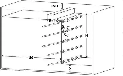
Figure 1. Schematic view of the soil box used in current study.
The height of the soil box must be selected so that its rigid bottom does not affect the model behavior. In this regard, if the depth of the soil layer is more than 2B from the bottom of footing, it will not affect the measured load bearing capacity of the footing (Pfeifle et al. 1979). However, some researchers have suggested minimum value of 4B for soil box height.
In this study, based on the size of centrifuge basket and the aforementioned considerations, we used a box with internal dimensions of 0.5 m in height, 0.8 m in length and 0.4 m in width. In one of the lateral sides of the box, a transparent window made of plexi-glass with thickness of 40 mm was provided which allows taking photos during the experiments. It should be noted that the lateral deformation of the transparent side is negligible and does not affect the plane strain behavior of the model. The experiments were conducted under the centrifuge acceleration of 30 g (the geometrical scale factor is 30); therefore, based on the scaling similitude rules, a trench of 9 m high was tested. The height of the model nailed wall was 300 mm. Also, the length of the model in all experiments was 500 mm and its width was 400 mm. To reduce the boundary effect, a depth of 50 mm was accommodated between bottom of the wall and bottom of the box as shown in Figure 1.
2.1 Specifications of the soil
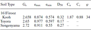
The soil used in physical model was Firooz Kooh sand no. 161. This sand is widely used as the standard soil for physical model testing in Iran (Bahadori et al. 2008). This sand has a uniform gradation similar to Japanese Toyora sand (Saber Mahani 2008). Physical and mechanical characteristics of this sand is presented in Table 1 in comparison with two other types of standard sand. In this table, Gs is the specific gravity of solid soil particles, emax & emin are the maximum and the minimum void ratios, D50 is the average particle size, Cu is the coefficient of uniformity, Cc is the coefficient of curvature and φ is the friction angle. Based on ASTM D2187 (2004), the soil used in this study is a medium sized sand which is designated as SP according to USCS. The model ground was constructed under controlled conditions based on the wet tamping method. The target relative density of the model ground was 60%.
Table 1. Characteristics of Firooz Kooh sand no. 161.
Table 2. Geometric and mechanical characteristics of the nails.
Property | |
Yield stress (kN/m2) | 100 × 103 |
Yield strain | 100 × 10–6 |
Modulus of Elasticity (kN/m2) | 55 × 106 |
Area (mm2) | 12.57 |
2.2 Specifications of the footings
The footings used in physical models were made of Aluminum with dimensions of 500 mm × 398 mm (W×L) and 750 mm × 398 mm (W×L). In order to avoid unwanted deflections in the footings, the vertical loading was uniformly applied on the footings through a rectangular steel bar having the same size as the footing.
2.3 Specifications of the nails
Considering the index properties of the soil (i.e. D50 = 0.32 mm), minimum nail diameter is 4.8 mm and 11.2 mm, based on Ovesen (1975) and Miligan and Tei et al. (1993) criteria, respectively. In this study, aluminum nails with 5 mm outside diameter and 3 mm inside diameter were used due to practical limitations and ease of nail placement in the model ground. Mechanical and geometric characteristics of Aluminum nails are presented in Table 2. The lengths of the nails were 200 mm and 150 mm. The head of each nail was threaded for installing a nut at its contact point to the wall facing. For continuity of movement between the facing and the nail, a plastic washer was used between the nut and the facing. To properly simulate the injection area around the nails, a thin layer of sand was glued to their outer surface.
2.4 Specifications of the facing
In order to avoid local failure in soil slopes, using a facing is necessary. Based on the results of previous studies (Sharifinejad 2012), the facing used in this ...