- 704 pages
- English
- ePUB (mobile friendly)
- Available on iOS & Android
eBook - ePub
About this book
Electric relays pervade the electronics that dominate our world. They exist in many forms, fulfill many roles, and each have their own behavioral nuances and peculiarities. To date, there exists no comprehensive reference surveying the broad spectrum of electric relays, save one-Electric Relays: Principles and Applications. This ambitious work is not only unique in its scope, but also in its practical approach that focuses on the operational and functional aspects rather than on theory and mathematics.
Accomplished engineer Dr. Vladimir Gurevich builds the presentation from first principles, unfolding the concepts and constructions via discussion of their historical development from the earliest ideas to modern technologies. He uses a show-not-tell approach that employs nearly 1300 illustrations and reveals valuable insight based on his extensive experience in the field. The book begins with the basic principles of relay construction and the major functional parts, such as contact and magnetic systems. Then, it devotes individual chapters to the various types of relays. The author describes the principles of function and construction for each type as well as features of several relays belonging to a type that operate on different principles.
Remarkably thorough and uniquely practical, Electric Relays: Principles and Applications serves as the perfect introduction to the plethora of electric relays and offers a quick-reference guide for the experienced engineer.
Trusted by 375,005 students
Access to over 1 million titles for a fair monthly price.
Study more efficiently using our study tools.
Information
1
History
______________
1.1 Relays and Horses
What is a relay?
There is probably no engineer or technician who would admit to his colleagues that he does not know what a relay is. It is an element so widely used in engineering that every engineer has had an opportunity to deal with it to some extent. Just for the sake of experiment try to define the notion “relay”… I don’t think you will be able to do so at the first attempt, nor the second, and if you try to look up the word in a dictionary you will be puzzled even more.
See for yourself:
Relay
- A fresh team of horses, posted at intervals along a route to relieve others
- A series of persons relieving one another or taking turns; shift
- To work in shifts
- A sport race
- A system of shifts at an enterprise
- To provide with or replace by fresh relays
- To retransmit
- A switch.
Quite unexpected, so many different definitions of a word so widely used in the field of engineering. What’s the explanation?
Let us start from the very beginning…
America’s first “railway line” from Baltimore to Ellicott’s factory was constructed in 1830. Its rail mileage was 13 miles. Trains consisted of several vans with wooden wheels pulled on wooden rails by a team of horses. Before long, such trains began to take people to far more distant towns. At the same time there had to be stopovers, for breaks to feed and rest horses. Such breaks considerably prolonged the journey until it occurred to someone that horses could be relieved at midpoint so that the journey could proceed with hardly any breaks at all. Each fresh team of horses was known as a “relay,” from the French word “relais,” which means replacement. The same name was given to the small town located at the “relay” point where the horses were changed for the first time.
Although horsed vans may have little to do with modern trains, the date of that event, August 28, 1830, is considered to be the beginning of the era of railroads in the U.S.A. It was on that day that horsed vans began to circulate regularly via Relay station. In 1872, a special railroad station (a retransmitting station) was built in Relay (Figure 1.1). It had comfortable rest rooms for passengers along with a view of a viaduct, Viaduct Hotel, and the Town Hall.
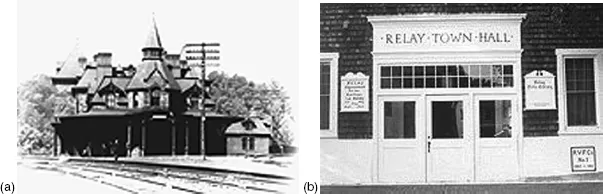
(a) Railroad station “Viaduct Hotel” and (b) the Town Hall in Relay.
At about the same time, some other remarkable events occurred, mostly in the same country but in quite a different field of human activity.
1.2 From Oersted to Henry
In 1820, the Danish physicist Hans Christian Oersted demonstrated for the first time that the interaction between a magnetic field and an electric current shows a slight impact of a single conductor on a compass needle. A few months later, during his experiments with a compass, the German scientist Schweigger, Professor of Chemistry at the University of Halle, noticed the fact that it is impossible to strengthen that influence by lengthening the conductor, because the compass will only interact with the nearest part of the wire. At that point it occurred to him to try to create a structure that would enable all the sections of the long wire to interact with the compass needle. He wound the long wire on a mandrel consisting of two studs, Aa and Cc, with the slots t and d in the form of several coils, attached outputs K and Z to a galvanic battery, and inserted the coils into the compass. He called this device a galvanic multiplier (Figure 1.2).
This was how the first prototype of an electromagnet was created, and if we put the compass in the B area as Professor Schweigger did, the multiplier becomes a galvanometer, enabling us to measure current strength and voltage. But this fact was unknown at that time, even to the inventor himself, the creator of this idea.
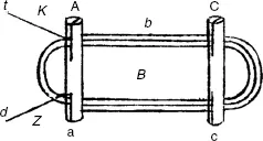
Schweigger’s galvanic multiplier (From Journal für Chemie und Physik 31, Neue Reihe, Bd. I, 1821.)
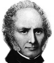
William Sturgeon (1783–1850).
Unfortunately such a considerable decrease in the deflection of the needle was observed, even within 200 lb, that it was obvious that the scheme was inadequate.
At that point it seemed that Barlow’s merciless verdict had put paid to the new telecommunication system suggested by Ampere.
The idea was appreciated to some extent by the outstanding French physicist Andre-Marie Ampere, who suggested applying Schweigger’s multiplier to something similar to a telegraph or telephone system, where every letter and figure was transmitted through a separate circuit, with the compass needle becoming an indicator of current in circuits corresponding to the letters and figures.
Ampere declared that his experiments were successful, although he did not provide any commentary. Perhaps there was no need to comment. At any rate, in 1824 the English scientist Peter Barlow, commenting on Ampere’s experiments, wrote that the components of the device were so obvious and the principle on which it was based so clear, that the only discovery needed was to find out whether electric current would be able to deflect the needle after passing through a long wire.
Fortunately the English scientist William Sturgeon (Figure 1.3), was unaware of Barlow’s point of view. He did not give up his research on electromagnetism. On the contrary, he made every possible effort to try to find a way to increase the power of the electromagnet. Success was immediate. In 1824 he published the description of his new electromagnet, consisting of an iron core and a coil of bare copper wire. In order to enable winding a large number of turns, Sturgeon coated the surface of the horseshoe-shaped iron core with varnish, and then wrapped the spiral coil of bare copper wire, with the turns not touching each other (Figure 1.4).
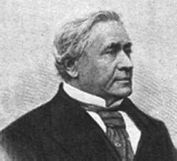
At that point a new personage appeared in this tale: Joseph Henry, Professor of Mathematics and Natural Philosophy at the Albany Academy in New York (Figure 1.5).
Even from the point of view of modern science Henry’s idea could be considered brilliant. He suggested insulating wire for an electromagnet by wrapping it with silk, and thus electrical wire was invented. From then on electromagnet coils were wound in hundreds of turns of insulated wire, and electromagnets were to become powerful devices widely used in many different experiments (Figure 1.6).
Soon after, Henry constructed the most powerful electromagnet in the world up to that time, which carried the weight of 7501b. He sent descriptions of his experiments to Benjamin Silliman, Professor of Chemistry and Natural History at Yale College and editor of The American Journal of Science. Silliman appreciated Henry’s work and in January 1831 he published in The American Journal of Science an article titled “Henry’s Albany magnet with its battery and apparatus for measuring its strength.” In addition to his report, Henry proposed making a demonstrational electromagnet for his future experiments and lectures, which would lift 1000 or 1200 lb.
(a) Sturgeon’s electromagnet. The horseshoe-shaped core with winding is at the top of the construction. (From Transactions of the Society for the Encouragement of the Arts, 43, 1824.) (b) Sturgeon’s electromagnets. (From William Sturgeon, Scientific Researches, Experimental and Theoretical, in Electricity, Magnetism, Galvanism, Electro-Magnetism and Electro-Chemistry, Bury, T. Crompton, 1850.)
Benjamin Silliman accepted his proposal and in a few months Henry constructed his magnet, which surpassed even his own expectations.
This “Yale magnet” with an iron core weighing 59 lb could carry the unprecedented weight of 2063 lb. As a token of gratitude Benjamin Silliman published a detailed description of Henry’s latest and most powerful magnet. In his editor’s notes he mentioned that Henry had managed to create an electromagnet eight times more powerful than ever before.
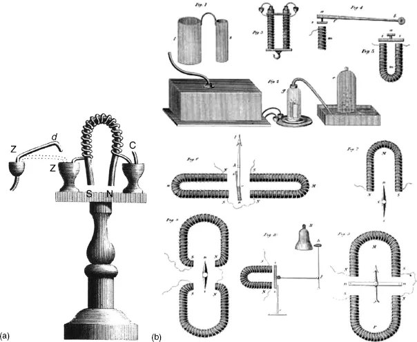
Some time later, in another one of his articles, Henry put forward the idea of making a machine that could be moved by an electromagnet, an idea closely connected with the future idea of transmission of power at a distance with the help of an electromagnet.
In the summer of 1831, Henry described technical solutions for these problems in a short article titled, “On a reciprocating motion produced by magnetic attraction and repulsion.” This was a simple device with a straight electromagnet rocking on a horizontal axis (Figure 1.7). Its motion automatically reversed its polarity as two pairs of wires projecting from the ends made connections, alternately, with two electrochemical cells. Two vertical permanent magnets, C and D, alternately attracted and repelled the ends of the electromagnet, making it rock back and forth at 75 vibrations per minute. In fact, this device already comprised all of the basic components of an electric device known today as a polarized electromagnetic relay: a coil, a ferromagnetic core, a permanent magnet, and contacts for switching the electric circuit. Unfortunately, Henry failed to distinguish that he had a prototype for a modern relay in his device. He considered it merely a “philosophical toy,” although useful for demonstrating the principles of electromagnetism to his students.
Prof...
Table of contents
- Cover Page
- Half Title
- Author
- Title Page
- Copyright Page
- Dedication
- Introduction
- Acknowledgments
- Preface
- 1 History
- 2 Magnetic Systems of Relays
- 3 Contact Systems
- 4 External Design of Relays
- 5 Reed Switches and Reed Relays
- 6 High-Voltage Relays
- 7 Electronic Relays
- 8 Time Relays
- 9 Thermal Relays
- 10 Protective Current and Voltage Relays
- 11 Power and Power Directional Relays
- 12 Differential Relays
- 13 Distance Relays
- 14 Frequency Relay
- 15 Microprocessor-Based Relays: Prospects and Challenges
- 16 Special Relays
- Basic Relay Terms and Definitions — Glossary
- References
- Index
Frequently asked questions
Yes, you can cancel anytime from the Subscription tab in your account settings on the Perlego website. Your subscription will stay active until the end of your current billing period. Learn how to cancel your subscription
No, books cannot be downloaded as external files, such as PDFs, for use outside of Perlego. However, you can download books within the Perlego app for offline reading on mobile or tablet. Learn how to download books offline
Perlego offers two plans: Essential and Complete
- Essential is ideal for learners and professionals who enjoy exploring a wide range of subjects. Access the Essential Library with 800,000+ trusted titles and best-sellers across business, personal growth, and the humanities. Includes unlimited reading time and Standard Read Aloud voice.
- Complete: Perfect for advanced learners and researchers needing full, unrestricted access. Unlock 1.4M+ books across hundreds of subjects, including academic and specialized titles. The Complete Plan also includes advanced features like Premium Read Aloud and Research Assistant.
We are an online textbook subscription service, where you can get access to an entire online library for less than the price of a single book per month. With over 1 million books across 990+ topics, we’ve got you covered! Learn about our mission
Look out for the read-aloud symbol on your next book to see if you can listen to it. The read-aloud tool reads text aloud for you, highlighting the text as it is being read. You can pause it, speed it up and slow it down. Learn more about Read Aloud
Yes! You can use the Perlego app on both iOS and Android devices to read anytime, anywhere — even offline. Perfect for commutes or when you’re on the go.
Please note we cannot support devices running on iOS 13 and Android 7 or earlier. Learn more about using the app
Please note we cannot support devices running on iOS 13 and Android 7 or earlier. Learn more about using the app
Yes, you can access Electric Relays by Vladimir Gurevich in PDF and/or ePUB format, as well as other popular books in Technology & Engineering & Electrical Engineering & Telecommunications. We have over one million books available in our catalogue for you to explore.