![]()
1
Basic Principles of Radiofrequency Identification
CONTENTS
1.1 Basics of RFID
1.2 Passive versus Active RFID Systems
1.3 Functional Classification of RFID Transponders
1.4 Applications and Frequency Selection
Although the widespread use of radiofrequency identification (RFID) is recent, the technology itself is several years old. RFID was first developed during World War II in order to distinguish between friend and enemy aircraft. Several years later, thanks to the technological advances in microelectronics, wireless communications, and computer networks, RFID has come of age. It has now become a technology that is mature enough to be mass-marketed at competitive cost and become a critical player in the global market. This chapter introduces the reader to the different parts that make up a RFID system and provides an overview of the different concepts that will be described in depth in the upcoming chapters.
1.1 Basics of RFID
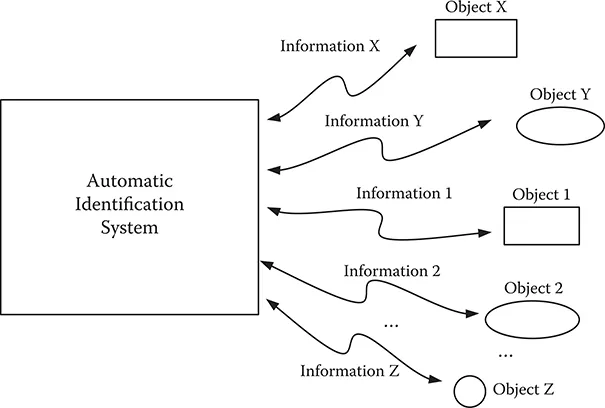
The basic function of an RFID system is to automatically retrieve the information that has been previously inserted into specific integrated circuits, as seen in Figure 1.1. RFID systems were first developed in automatic identification laboratories as a natural evolution of the different technologies they use. Different automatic identification systems use different methods to transmit the identifying information. For example, bar code technology uses light as the transmission media, while RFID systems use radio waves. In this context, the two main elements of RFID systems are the devices used to carry this information and the equipment used to automatically capture or retrieve the information.
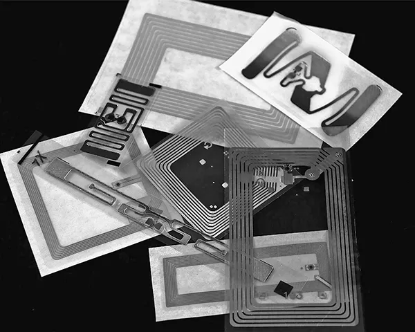
The devices that store and carry the information are called transponders or tags and are shown in Figure 1.2. Although the industry commonly refers to them as tags mainly due to their physical shape and the fact that they are mostly used to tag pallets or cases of goods, the name transponder reflects better the function of these devices.
FIGURE 1.1 Information transfer in an automatic identification system.
FIGURE 1.2 Several types of transponders used in RFID systems.
The device that is used to capture and transfer information is commonly called a reader, because in earlier RFID systems they were only able to read the information sent by the transponders. However, with the development of new functions and applications of RFID systems, the name interrogator reflects better the function of this subsystem. Therefore, this book will use the names transponder and interrogator when referring to these elements.
Transponders must have the circuitry needed to harvest power from the electromagnetic fields generated by the interrogator, the necessary memory elements, as well as the different control circuits. The simplest transponders contain only read-only memory (ROM), while more sophisticated transponders also include random access memory (RAM) and nonvolatile programmable read-only memory (PROM) or electrically erasable programmable read-only memory (EEPROM). ROM usually contains the identification string for the transponder and instructions for its operating system. RAM is normally used for temporary data storage when the transponder communicates with the interrogator. PROM or EEPROM is normally used to incorporate additional functionality depending on the application. The memory capacity of transponders ranges from a single bit to several kilobits. Single-bit transponders are typically used in retail electronic surveillance in which there are only two possible states: article paid and article not paid. Memory sizes of up to 128 bits are enough to store the individual transponder identification number with several check bits. Memories up to 512 bits are normally user programmable, in which in addition to the individual identification number the memory can hold additional information required by its application. Higher capacity memories can be seen as carriers for the transport of data files. They are also used in applications in which there are several sensors attached to the transponder.
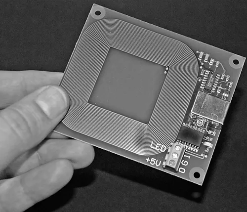
Interrogators have vastly different complexity levels depending on the type of transponders they support as well as their specific purpose. In any case, they all must provide the basic functionality to communicate with the transponders, first by energizing them and second by establishing a communications link. The complexity of the communications link can also vary considerably depending on the desired reliability. The reliability of the communications link between transponder and interrogator can be enhanced by adding parity checks, error detection, and error detection and correction. However, the use of these schemes will result in a lower transmission rate. Figure 1.3 shows a picture of a basic interrogator in which it is possible to see the coiled antenna and some of the electronic circuits.
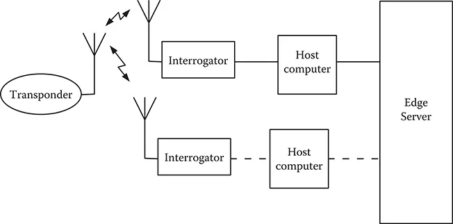
RFID systems contain more elements in addition to the transponder and interrogator. First, the communication between transponder and interrogator is not possible—or becomes extremely deficient—without the appropriate radiant elements that will transfer the information between these two subsystems in the form of electromagnetic energy. Both transponder and interrogator need to use the appropriate antennas to transfer information. As will be discussed in Chapter 2, the antenna dimensions in commercially available transponders and interrogators are much shorter than their ideal dimensions. This results in seriously limiting the transfer of energy between interrogators and transponders.
FIGURE 1.3 Basic RFID interrogator operating in the low-frequency (LF) range.
In addition to the transponders, the interrogators, and their antennas, the RFID system requires a host computer connected to the interrogator. This host computer provides a certain level of intelligence and acts like the interface between the RFID system and the ultimate application. Therefore, the interrogator must have the means to at least perform basic communication functions with the interrogator. A large number of today’s applications require more than one interrogator running on a network rather than the single, stand-alone interrogator that was typical of earlier systems. Finally, an edge server is normally used between the host computer and the network in which the application is running.
In addition to these elements (shown in Figure 1.4), most of them hardware based, a typical RFID system contains several software elements. The firmware is the software that runs inside the interrogator in order to provide it with its basic functions. Some interrogators may also run one or more software applications that enhance the versatility of the interrogator. The name middleware encompasses the software applications that run in the background of the system, typically after the host computer. Finally, most applications require the use of one or several databases used to link the stored message sent by the transponder with more detailed information that can identify the transponder and provide additional information.
FIGURE 1.4 Basic structure of an RFID system.
1.2 Passive versus Active RFID Systems
Passive RFID systems are those systems that use passive transponders. Passive transponders do not have an internal power source. They harvest the energy needed by their internal circuits from the electromagnetic field generated by the interrogator. For this reason, they have a short range, limited to a few feet and often, more realistically, to a few inches. Because they don’t have an internal source of energy, the user does not need to worry about the status of the battery. Furthermore, their manufacturing and production costs are very low. The RFID transponders and systems described in this book are all passive.
Active RFID systems, on the other hand, use active transponders. Active transponders have an internal power source, typically a battery that allows broadcasting the signal to the interrogator. Because of not being limited to the power harvested by the antenna, they have an extended read range, typically several hundred feet. However, the inclusion of the power source increases their cost in two ways: the cost of the battery itself as well as the maintenance costs required to check the status of the internal power source and replace it when it has reached an unacceptably low level. The cost of an active transponder is approximately 100 times higher than the cost of a passive transponder. Active transponders typically operate in the ultra-high-frequency (UHF) and microwave ranges. A new type of active RFID transponder is linked to the use of RFID-enabled cell phones that can emulate an active tag. In this case, the problem of battery maintenance is solved as the user keeps the cell phone charged as part of its regular maintenance.
A third type of transponder is called semipassive or battery-assisted transponder. These transponders also include a battery, but contrary to active transponders, the battery is not used to generate the power to transmit the signal to the interrogator. Instead, the battery is used to support secondary functions like the data logging from different types of sensors. These transponders also harvest the energy from the electromagnetic field generated by the interrogator to power its internal circuits other than the sensing and data-logging parts.
1.3 Functional Classification of RFID Transponders
A functional classification of RFID transponders is based on their electronic product code (EPC) class. EPC is the application of one specific type of RFID technology within the consumer packaged goods industry. Within this classification, RFID transponders are divided into different classes and generations:
Generation 1, Class 0: Passive tags with read-only functionality. These are also called write one, read many (WORM) transponders. These transponders are programmed at the factory with their unique identification number. The user is not able to change it or include additional information.
Generation 1, Class 0+: These are also WORM transponders. They differ from Generation 1, Class 0 transponders in that it is the user who programs them. After they have been programmed by the user, no further programming or changing of data is allowed.
Generation 1, Class 1: These transponders were similar to Generation 1, Class 0 or 0+ transponders, but could be read by interrogators from other companies. Gen 1, Class 1 transponders have evolved into the different transponders from Generation 2.
Whereas Generation 1 transponders employ proprietary data structures and can be read only by interrogators manufactured by the same vendor, Generation 2 transponders are vendor neutral in their specifications. This means that as they have developed (following agreed upon standards), they can be read with interrogators from multiple vendors. These transponders provide additional features, for example the elimination of duplicate reads within the read range. They are also more reliable than Generation 1 transponders and support faster read rates. The user of...