- 512 pages
- English
- ePUB (mobile friendly)
- Available on iOS & Android
eBook - ePub
Lens Design
About this book
There is no shortage of lens optimization software on the market to deal with today's complex optical systems for all sorts of custom and standardized applications. But all of these software packages share one critical flaw: you still have to design a starting solution. Continuing the bestselling tradition of the author's previous books, Lens Design, Fourth Edition is still the most complete and reliable guide for detailed design information and procedures for a wide range of optical systems.
Milton Laikin draws on his varied and extensive experience, ranging from innovative cinematographic and special-effects optical systems to infrared and underwater lens systems, to cover a vast range of special-purpose optical systems and their detailed design and analysis. This edition has been updated to replace obsolete glass types and now includes several new designs and sections on stabilized systems, the human eye, spectrographic systems, and diffractive systems. A new CD-ROM accompanies this edition, offering extensive lens prescription data and executable ZEMAX files corresponding to figures in the text.
Filled with sage advice and completely illustrated, Lens Design, Fourth Edition supplies hands-on guidance for the initial design and final optimization for a plethora of commercial, consumer, and specialized optical systems.
Trusted by 375,005 students
Access to over 1 million titles for a fair monthly price.
Study more efficiently using our study tools.
Information
1 | The Method of Lens Design |
Given an object and image distance, the wavelength region and the degree of correction for the optical system, it would at first appear that with the great progress in computers and applied mathematics it would be possible to analytically determine the radius, thickness, and other constants for the optical system. Neglecting very primitive systems, such as a one- or two-mirror system, or a single-element lens, such a technique is presently not possible.
The systematic method of lens design in use today is an iterative technique. By this procedure, based upon the experience of the designer, a basic lens type is first chosen. A paraxial thin lens and then a thick lens solution is next developed. In the early days of computer optimization, the next step was often correcting for the third-order aberrations (Hopkins et al. 1955). Now, with the relatively fast speed of ray-tracing, this step is often skipped and one goes directly to optimization by ray-trace.
In any automatic (these are really semi-automatic programs because the designer must still exercise control) computer-optimization program, there must be a single number that represents the quality of the lens. Because the concept of a good lens vs. a bad lens is always open to discussion, there are thus several techniques for creating this merit function (Feder 1957a,1957b; Brixner 1978). The ideal situation is a merit function that considers the boundary conditions for the lens as well as the image defects. These boundary conditions include such items as maintaining the effective focal length (or magnification), f-number, center and edge spacings, overall length, pupil location, element diameters, location on the glass map, paraxial angle controls, paraxial height controls, etc. There should also be a means to change the weights of these defects so that the axial image quality may be weighted differently than the off-axis image, as well as means for changing the basic structure of the image (core vs. flare, distortion, chromatic errors, etc.) (Palmer 1971). Some merit functions also contain derivative data (Feder 1968).
Most optimization and analysis programs in use today evaluate the optical system by means of ray tracing (Jamieson 1971). However, some compute the aberration coefficients (third and higher orders) at each surface and then form the sum (Buchdahl 1968).
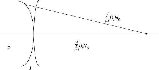
In the early days of optical design, when the cost of tracing a ray was high (as compared to today), a common technique to reduce the number of rays traced was to only trace rays at the central wavelength and carry thru, at each surface, information regarding path-length differences multiplied by the difference in dispersion (Feder 1952; Conrady 1960; Ginter 1990).
Let dI be the distance along the axis from surface I to surface I + 1 and let DI be the distance for an arbitrary ray from surface I to surface I + 1. Then for a system of J surfaces, and (ND)I as the refractive index for the central wavelength following surface I,
For a spherical wavefront centered at P,
and likewise for the extreme wavelengths, F and C, to be united at P. To be achromatic,
As an example of a merit function, let d be a defect item—the departure on the image surface between the traced rays and its idealistic or Gaussian value (or other means for determining the center of the image). Alternatively, one may use path-length errors as a defect item. The ideal situation is to use a combination of both intercept and path-length errors in the merit function because path-length errors may be obtained with only a small amount of extra computing time, while the rays will be traced.
,
where k is a proportionally constant. The intercept errors are then approximately proportional to the derivative of the path-length errors. It is also sometimes helpful to add differential errors to the merit function. For example, if J rays are traced at a particular field angle and wavelength, then
where Pl(J) is the path-length for the J ray. Because the major load in optimization is the tracing of rays, these extra items improve the image while adding only slightly to computer time. These defect items will be weighted by a factor W to permit us to control the type of image we desire. If there are N defect items, then
Most merit functions are really “demerit” functions, i.e., they represent the sum of squares of various image errors. Therefore, the larger the number, the worse the image. The input system is ray traced, and the merit function is computed. One of the permitted parameters is then changed, and a new value of the merit function is calculated. A table is then created of merit function changes vs. parameter c...
Table of contents
- Cover
- Half Title
- Title Page
- Copyright Page
- Dedication
- Table of Contents
- Chapter 1 The Method of Lens Design
- Chapter 2 The Achromatic Doublet
- Chapter 3 The Air-Spaced Triplet
- Chapter 4 Triplet Modifications
- Chapter 5 Petzval Lenses
- Chapter 6 Double Gauss and Near Symmetric Types
- Chapter 7 Telephoto Lenses
- Chapter 8 Inverted Telephoto Lens
- Chapter 9 Very-Wide-Angle Lenses
- Chapter 10 Eyepieces
- Chapter 11 Microscope Objectives
- Chapter 12 In-Water Lenses
- Chapter 13 Afocal Optical Systems
- Chapter 14 Relay Lenses
- Chapter 15 Catadioptric and Mirror Optical Systems
- Chapter 16 Periscope Systems
- Chapter 17 IR Lenses
- Chapter 18 Ultraviolet Lenses and Optical Lithography
- Chapter 19 F-Theta Scan Lenses
- Chapter 20 Endoscope
- Chapter 21 Enlarging and Copying Lenses
- Chapter 22 Projection Lenses
- Chapter 23 Telecentric Systems
- Chapter 24 Laser-Focusing Lenses (Optical Disc)
- Chapter 25 Heads-Up Display Lenses
- Chapter 26 The Achromatic Wedge
- Chapter 27 Wedge-Plate and Rotary-Prism Cameras
- Chapter 28 Anamorphic Attachments
- Chapter 29 Illumination Systems
- Chapter 30 Lenses for Aerial Photography
- Chapter 31 Radiation-Resistant Lenses
- Chapter 32 Lenses for Microprojection
- Chapter 33 First-Order Theory, Mechanically Compensated Zoom
- Chapter 34 First Order Theory, Optically Compensated Zoom Lenses
- Chapter 35 Mechanically Compensated Zoom Lenses
- Chapter 36 Optically Compensated Zoom Lenses
- Chapter 37 Copy Lenses with Variable Magnification
- Chapter 38 Variable Focal Length Lenses
- Chapter 39 Gradient-Index Lenses
- Chapter 40 Stabilized Optical Systems
- Chapter 41 The Human Emmetropic Eye
- Chapter 42 Spectrographic Systems
- Chapter 43 Diffractive Systems
- Appendix A Film and CCD Formats
- Appendix B Flange Distances
- Appendix C Thermal and Mechanical Properties
- Appendix D Commercially Available Lens Design Programs
- Index
Frequently asked questions
Yes, you can cancel anytime from the Subscription tab in your account settings on the Perlego website. Your subscription will stay active until the end of your current billing period. Learn how to cancel your subscription
No, books cannot be downloaded as external files, such as PDFs, for use outside of Perlego. However, you can download books within the Perlego app for offline reading on mobile or tablet. Learn how to download books offline
Perlego offers two plans: Essential and Complete
- Essential is ideal for learners and professionals who enjoy exploring a wide range of subjects. Access the Essential Library with 800,000+ trusted titles and best-sellers across business, personal growth, and the humanities. Includes unlimited reading time and Standard Read Aloud voice.
- Complete: Perfect for advanced learners and researchers needing full, unrestricted access. Unlock 1.4M+ books across hundreds of subjects, including academic and specialized titles. The Complete Plan also includes advanced features like Premium Read Aloud and Research Assistant.
We are an online textbook subscription service, where you can get access to an entire online library for less than the price of a single book per month. With over 1 million books across 990+ topics, we’ve got you covered! Learn about our mission
Look out for the read-aloud symbol on your next book to see if you can listen to it. The read-aloud tool reads text aloud for you, highlighting the text as it is being read. You can pause it, speed it up and slow it down. Learn more about Read Aloud
Yes! You can use the Perlego app on both iOS and Android devices to read anytime, anywhere — even offline. Perfect for commutes or when you’re on the go.
Please note we cannot support devices running on iOS 13 and Android 7 or earlier. Learn more about using the app
Please note we cannot support devices running on iOS 13 and Android 7 or earlier. Learn more about using the app
Yes, you can access Lens Design by Milton Laikin in PDF and/or ePUB format, as well as other popular books in Technology & Engineering & Electrical Engineering & Telecommunications. We have over one million books available in our catalogue for you to explore.