![]()
1
Introduction
Synthetic aperture radar (SAR), originating fin 1950s, is a form of radar imaging technology which utilizes the relative motion between an antenna and its target region to simulate an extremely large antenna or aperture electronically, and which generates finer spatial resolution than that is possible with conventional beam-scanning means [211]. It is usually implemented by mounting radar on a moving platform such as airplane or satellite, from which a target scene is repeatedly illuminated with pulses of radio waves. The radar returns received successively at different antenna positions are coherently detected and stored and then post-processed together to resolve elements in an image of the target region.
One of the main advantages for SAR imaging is the ability to operate in almost any weather, day or night, thereby overcoming many of the limitations of other passive imaging technologies such as optical and infrared. SAR can also be implemented as “inverse SAR” by observing a moving target over a substantial time with a stationary antenna. As single-antenna SAR is a well- proven remote sensing technique [51, 386], this book concentrates only on multi-antenna SAR systems and signal processing. The SAR basics can be found in several excellent books [73, 76, 353].
This chapter is organized as follows. Several basic concepts related to multi-antenna SAR imaging are introduced in Section 1.1, where several multiantenna SARs and their system characteristics are discussed. The benefits of multi-antenna SAR, as compared to conventional single-antenna SAR, is investigated in Section 1.2. This is followed by the advances in monostatic and distributed multi-antenna SAR imaging in Section 1.3. Finally, the organization of this book is outlined in Section 1.4.
1.1 What is Multi-Antenna SAR
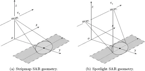
Conventional single-antenna stripmap and spotlight SAR systems (see Figure 1.1) are inherently limited in meeting the rising demands of future remote sensing missions. Innovative SAR imaging techniques are thus needed to be developed. The most promising of these techniques usually employ multiple antennas [161, 186, 187]. Multi-antenna SAR allows for simultaneous transmission and reception by multiple channels, compared to conventional SAR systems with only a single channel. This provides a potential to gather additional information and to benefit from this information to overcome the restrictions of conventional SAR systems.
FIGURE 1.1: General stripmap and spotlight SAR geometries.
Multiple antennas can be placed either in a monostatic platform which results in a monostatic multi-antenna SAR system or in distributed platforms which results in a distributed multi-antenna SAR system. In the following, we introduce them separately.
1.1.1 Multichannel SAR
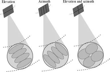
Multiple antennas can be either arranged in flight direction (“along-track”) [77], perpendicular to it (“cross-track”) [164], or in both dimensions [45]. They are illustrated, respectively, in Figure 1.2.
1.1.1.1 Multiple Channels in Elevation
The concept of multiple channels in elevation dimension proposed by Griffiths and Mancini [164] consists of an array antenna split in elevation dimension. The overall antenna dimension is smaller than that implied by the minimum antenna area constraint yielding a broad beam in elevation dimension that covers a wide swath (the ground width covered by the SAR beam) but at the same time gives rise to range ambiguous echoes. The range ambiguities can be suppressed by adaptively steering nulls in the antenna pattern in elevation to the directions of the ambiguous returns. In this way, a widened imaging swath can be obtained; however, in a monostatic SAR the swath may become no longer continuous because blind ranges will be introduced when the receiver is switched off during transmission. Such restrictions could be overcome with bistatic geometry which allows for simultaneous transmission and reception [217, 218] and hence, short compact antennas could be used for high resolution SAR systems with continuous wide area coverage.
FIGURE 1.2: Typical configurations of the multiple antennas in monostatic multi-antenna SARs..
In 2001, Suess et al. [361] proposed an innovative SAR which is built on an array antenna consisting of multiple elements in elevation. The proposed processing algorithm combines the echoes from the multichannel SAR in a way that forms a narrow beam in elevation which “scans” the ground in real-time in order to follow the returns of the transmitted signal. This enables a suppression of range ambiguous returns and ensures a high antenna gain. However, this technique requires knowledge of the observed terrain topography, otherwise a mispointing of the narrow elevation beam may occur, resulting in severe system gain loss [216].
1.1.1.2 Multiple Channels in Azimuth
In 1992, Currie and Brown [77] proposed the displaced phase center antenna (DPCA) in azimuth technique, which is based on dividing the receiving antenna in the along-track direction into multiple subapertures, each receiving, down-converting and digitizing the radar echoes. Hence, for every transmitted pulse the system receives multiple pulses in the along-track direction. This means that additional samples can be gathered, thus increasing the effective sampling rate. Consequently, either the azimuth resolution can be improved while the swath width remains constant, or the swath can be widened without increasing the azimuth ambiguities or impairing the azimuth resolution. That is to say, the system benefits from the whole antenna length regarding azimuth ambiguity suppression while azimuth resolution is determined by the dimension of a single subaperture, thus decoupling the restrictions on high-resolution and wide-swath remote sensing. This technique recovers the azimuth signal by simply interleaving the samples of the different receiving channels without any further processing, but it imposes a stringent timing requirement on the system regarding the relation between platform velocity, pulse repetition frequency (PRF) and antenna length [145]. These parameters have to be adjusted in order to obtain a signal that is equivalently sampled as a single-aperture signal at the same effective sampling rate.
1.1.1.3 Multiple Channels in Azimuth and Elevation
In 1999, Callaghan and Longstaff [45] proposed the quad array concept which is based on an antenna split into two rows and two columns yielding a four- element array. This approach can be understood as a combination of the two approaches described previously. It combines the advantages of gathering additional samples in azimuth to suppress azimuth ambiguities and simultaneously enabling an enlarged swath for a fixed PRF. This system may result in blind ranges in the imaged swath. Additionally, it requires also a stringent timing constraint to ensure a uniform spatial distribution of the sampled signals in azimuth dimension.
In addition, Classen and Eckerman [65] proposed an alternative concept which is based on steering multiple beams to different azimuth directions and assigning each of the corresponding footprints to a different slant range. In other words, the footprint of each beam steered to a different squint angle corresponds to a different subswath of the overall imaged region. As the antenna elevation dimension is larger than the imaged swath, range ambiguities can be well suppressed, thus allowing for a PRF high enough to suppress azimuth ambiguities. But, there will be coarsened resolution and impaired performance arising from the needed high squint angles [187].
1.1.2 Multi-Antenna SAR
The earliest radars were bistatic, which employed continuous-wave waveforms and separate transmitting and receiving antennas [446]. However, the bistatic form of radar was largely abandoned as a design approach after the invention of the duplexer. This allows the colocation of transmitting and receiving antennas thus simplifying the radar system design complexity. In recent years, the use of opportunistic illuminators, such as the global positioning systems (GPS) [360, 420] and broadcasting satellites [66], is considered as a main trigger for the significant growth of bistatic radars [165]. The books authored by Willis [446] and Cherniakov [60, 61] provide an excellent summary of bistatic radars. Multistatic radar extends the bistatic concept by having more than two transmitters or receivers.
Multistatic SAR extends conventional multistatic radars by employing aperture synthesis. It should be noted that many different terms for multistatic SAR are used in literature. These include multistatic SAR, multi-antenna SAR, netted SAR, multisite SAR and distributed SAR. In this book, we use the term multi-antenna SAR as a “catch-all” to embrace all possible forms. Note that the term multistatic SAR has in the past been more typically used to refer to a distributed SAR network. We classify multistatic multi-antenna SAR into two types: single-input multiple-output (SIMO) SAR and multiple-input multiple-output (MIMO) SAR.
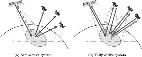
FIGURE 1.3: Example semi-active and fully active multistatic SIMO SAR systems.
1.1.2.1 SIMO Multi-Antenna SAR
In multistatic SIMO SAR systems, only a single waveform is transmitted by one or more antennas. Multistatic SIMO SAR systems can be realized with different platform pairs. For example, future SIMO SARs could use “receive only” receivers mounted on airplanes [397], ground [86], unmanned aerial vehicles, near-space vehicles [402], satellites, or both the transmitters and receivers are mounted on airplanes [301] or satellites [286]. Multistatic SIMO SAR systems can be further divided into semi-active and fully active configurations, as shown in Figure 1.3. Semi-active configuration combines passive receiver with an active radar illuminator; fully active configuration uses conventional radars flying in close formation to acquire data during a single pass. Both of the radars have a fully equipped radar payload with transmit and receive capabilities.
The simplest and most representative multistatic SIMO SAR is the bistatic SAR. In this book, we further classify bistatic SAR into azimuth-invariant and azimuth-variant configurations. Two typical azimuth-invariant configurations are the pursuit monostatic mode (see Figure 1.4 (a)), where the transmitter and receiver are flying along the same trajectory at an equal velocity, and the translational invariant mode (see Figure 1.4 (b)), where the transmitter and receiver are flying along parallel trajectories with the same velocity. An azimuth-invariant configuration can be seen as an equivalent monostatic configuration. In contrast, an azimuth-variant configuration cannot be seen as an equivalent monostatic configuration because the geometry betw...