- 504 pages
- English
- ePUB (mobile friendly)
- Available on iOS & Android
eBook - ePub
The Optical Transfer Function of Imaging Systems
About this book
The Optical Transfer Function of Imaging Systems deals extensively with the theoretical concept of the optical transfer function (OTF), its measurement, and application to imaging devices. The OTF is a mathematical entity describing how well the subject is transferred into an image via the lens.
The book focuses on the practical aspects of using and measuring the OTF. It presents the background physics necessary to understand and assess the performance of the great proliferation of electro-optical systems, including image intensifiers, video cameras, and thermal imagers.
Assuming a senior undergraduate level of optics knowledge, the book is suitable for graduate courses in optics, electro-optics, and photographic science. In addition, it is a practical guide for systems designers who require a means of assessing and specifying the performance of imaging systems. It is also of interest to physicists and engineers working in all areas of imaging.
Trusted by 375,005 students
Access to over 1.5 million titles for a fair monthly price.
Study more efficiently using our study tools.
Information
Chapter 1
The performance of imaging systems
1.1 Introduction
A wide variety of devices and systems exist whose main function is to generate an image. These devices and systems are used for many different purposes and find applications in many different walks of life. We are all very familiar with some of these systems such as the photographic camera (that can produce a permanent record of a scene on sensitized sheet material) and the television set (that can receive a suitably coded electromagnetic signal broadcast through space and convert it into an image). Less familiar are systems such as an image intensifier sight that is used to amplify the intensity of a very poorly lit scene (e.g. one lit only by starlight) so as to produce a brighter image that is clearly visible to an observer, or a thermal imaging camera that generates a visible image of an object from the infrared radiation that the object emits. Imaging systems find applications in science, medicine, industry, defence, surveillance, space, education, leisure and a host of other areas.
If an imaging device or system is to adequately perform the task for which it is intended, it must be capable of producing images of a certain minimum quality. The ability to be able to define this quality in objective terms is of importance to the user, the designer and the manufacturer of the imaging system.
Several different parameters are required to fully specify the performance of an imaging system. Some of these are very specific to particular types of system, whilst others are more generally relevant. This book is mainly concerned with one very important characteristic of all imaging devices, which is the ability to reproduce faithfully the relative intensity distribution of the original scene in the final image generated by the system. The parameter that is now used almost universally to describe this aspect of imaging is in fact the optical transfer function, hereafter referred to in this book simply as the OTF.
The aim of this book is to give the reader an understanding of what the OTF is, what factors determine its value for particular types of system, how the OTF of a device or system is determined theoretically, how it is measured (particular attention is paid to this aspect of the subject) and how the performance required of a system (i.e. its suitability for a specific task) can be related to an OTF value.
Very briefly, the OTF is a measure of how the contrast and phase of a sinewave grating pattern (i.e. one where the intensity perpendicular to the direction of the grating lines varies sinusoidally) is reproduced by the imaging system. The part of the OTF describing the reproduction of contrast is called the modulation transfer function (MTF), while the phase component is called the phase transfer function (PTF). Both the MTF and PTF are functions of the periodicity of the sinewave pattern. It was mentioned above that the performance of an imaging system depends on several parameters. This chapter provides an overview of some of these in order not only to provide the reader with a broader understanding of what is involved in fully specifying the performance of an imaging system, but also to provide a correct perspective for the particular parameter with which this book is mainly concerned, i.e. the OTF.
1.2 Parameters that determine the performance of imaging systems
1.2.1 What is performance?
The term ‘performance’ is used here to cover all aspects of an imaging system that have a bearing on its ability to perform a specific task. The task may be one that can be defined in relatively objective terms such as the ability to detect or track a certain object at a given range, or can be a subjective one such as the ability to produce a photograph that is pleasing to the observer.
The term ‘imaging quality’ is usually used in a more restrictive sense to describe the fineness of detail that can be resolved in the image and/or the sharpness of edges etc. This is only one of several performance parameters, although possibly the most important. It is the aspect of imaging to which the OTF relates.
1.2.2 Image brightness
The ability of a human observer to see and resolve detail in an object is very much a function of the brightness of the object he is looking at or, more strictly, the illuminance in the image relayed by the lens of the eye onto the retina.
The curves plotted in figure 1.1 show how the threshold of contrast for an observer to detect a bright disc against a darker background, varies with both the angular size (or area) of the disk and the background luminance. These curves are plotted from data obtained by Blackwell [1] in a series of classical experiments in which he used many observers. The definition of contrast used in these experiments is (L2−L1)/L1, where L1 is the luminance of the background and L2 is that of the disk (see figure 1.2). More recently, many experiments have been done to measure the threshold of contrast of the human observer for two-dimensional periodic patterns (i.e. gratings) of varying periodicity and luminance. Figure 1.3 shows the results of such a measurement [2] using patterns with a sinewave and squarewave variation in luminance. The experimental results have been plotted as ‘contrast sensitivity’ versus ‘spatial frequency’ for two different levels of average luminance. Contrast sensitivity, as used here, is simply the reciprocal of the threshold contrast where (as is usual for periodic patterns) contrast is defined as (L2−L1)/(L2+L1) (see figure 1.4). Spatial frequency is simply the reciprocal of the periodicity of the pattern and is expressed here as cycles/degree.
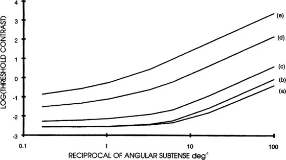
Figure 1.1. Threshold contrast for detection of a circular disc against a darker background as a function of the angular size of the disc and the luminance of the background, (a) 1000 ft. Lamberts, (b) 10 ft. Lamberts, (c) 0.1 ft. Lamberts, (d) 0.001 ft. Lamberts, (e) 0.00001 ft. Lamberts (Blackwell [1]).
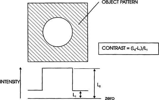
Figure 1.2. Contrast of a circular disc object.
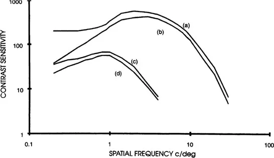
Figure 1.3. Contrast sensitivity curves for periodic patterns (gratings) as a function of spatial frequency and background luminance; (a) square-wave gratings: 500 cd/m2, (b) sine-wave gratings: 500 cd/m2, (c) square-wave gratings: 0.05 cd/m2, (d)sine-wave gratings: 0.05 cd/m2 (adapted from Campbell and Robson [2]).
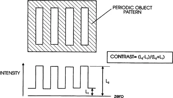
Figure 1.4. Contrast for a periodic grating pattern.
The curves clearly show that the contrast sensitivity of an observer is reduced as the luminance goes down and that the maximum spatial frequency that he can resolve is also reduced. The effect can be compounded in situations where the eye must exert some accommodation in order to see the image in proper focus since low levels of retinal illuminance will reduce the accommodation stimulus and a good focus may not be achieved.
The illuminance produced by a lens system in the image of an extended object can be shown to be given by (refer to figure 1.5):
(1.1) |
where we have: k = transmission of the lens system, L = luminance of the object, sin(ξ) = the numerical aperture (NA) of the lens system (note: f-number = 1/(2NA)).
Where the eye views an object directly through a purely optical instrument, such as a pair of binoculars (see figure 1.6) or a periscopic sight, the illuminance in the image on the retina depends on the luminance of the object, the transmission of the optical elements of the instrument and the diameter of the effective exit pupil (since the focal length of the eye lens is effectively fixed the NA at which it operates is proportional to the diameter of the effective pupil). In such an instrument the exit pupil will normally coincide with the eye pupil (i.e. the iris of the eye) and provided the exit pupil is larger than the pupil of the eye so that the latter is the effective pupil, the only instrumental factor that will affect the illuminance on the retina will be the transmission of the instrument.
Since the diameter of the eye pupil varies with the scene luminance, reaching diameters in excess of 7 mm at very low luminance levels, the performance of instruments with exit pupils less than this will be limited by the diameter of this exit pupil at lower levels of scene luminance.
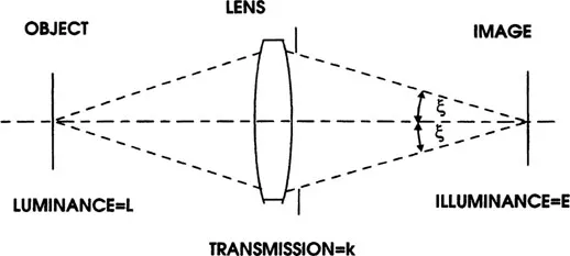
Figure 1.5. Illuminance in the image plane of a lens (see text).
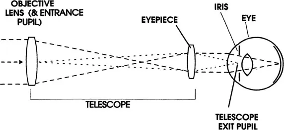
Figure 1.6. Position of the entrance and exit pupils in binoculars or telescopes, showing coincidence of the latter with the iris of the eye.
This is an important consideration in the design of this type of instrument since the size of the entrance pupil, and hence the diameter of the front objective lens, is equal to the product of the magnification and the exit pupil diameter. Binoculars ...
Table of contents
- Cover
- Half Title
- Title Page
- Copyright Page
- Table of Contents
- List of abbreviations
- List of symbols
- 1 The performance of imaging systems
- 2 An introduction to the OTF concept, its calculation and measurement
- 3 A review of techniques for measuring the OTF/MTF of lens systems
- 4 Measurement of the OTF/MTF of lens systems
- 5 Test conditions and other special considerations relating to specific classes of optical system
- 6 Photographic materials and systems
- 7 Electro-optical imaging devices and systems
- 8 Factors affecting the accuracy of OTF measurement and methods of assessing accuracy
- 9 OTF/MTF and image quality
- 10 MTF of sampled imaging systems
- 11 Veiling glare
- 12 Diagnostic and other applications of MTF equipment
- Appendix A Values for some useful functions
- Appendix B Data on sources and detectors, including photographic materials
- Appendix C Data for assessing the accuracy of MTF equipment in terms of NAV (nominal accuracy value)
- Appendix D Data for some standard test lenses
- Appendix E Incoherent illumination of MTF test patterns
- Bibliography
- Index
Frequently asked questions
Yes, you can cancel anytime from the Subscription tab in your account settings on the Perlego website. Your subscription will stay active until the end of your current billing period. Learn how to cancel your subscription
No, books cannot be downloaded as external files, such as PDFs, for use outside of Perlego. However, you can download books within the Perlego app for offline reading on mobile or tablet. Learn how to download books offline
Perlego offers two plans: Essential and Complete
- Essential is ideal for learners and professionals who enjoy exploring a wide range of subjects. Access the Essential Library with 800,000+ trusted titles and best-sellers across business, personal growth, and the humanities. Includes unlimited reading time and Standard Read Aloud voice.
- Complete: Perfect for advanced learners and researchers needing full, unrestricted access. Unlock 1.5M+ books across hundreds of subjects, including academic and specialized titles. The Complete Plan also includes advanced features like Premium Read Aloud and Research Assistant.
We are an online textbook subscription service, where you can get access to an entire online library for less than the price of a single book per month. With over 1.5 million books across 990+ topics, we’ve got you covered! Learn about our mission
Look out for the read-aloud symbol on your next book to see if you can listen to it. The read-aloud tool reads text aloud for you, highlighting the text as it is being read. You can pause it, speed it up and slow it down. Learn more about Read Aloud
Yes! You can use the Perlego app on both iOS and Android devices to read anytime, anywhere — even offline. Perfect for commutes or when you’re on the go.
Please note we cannot support devices running on iOS 13 and Android 7 or earlier. Learn more about using the app
Please note we cannot support devices running on iOS 13 and Android 7 or earlier. Learn more about using the app
Yes, you can access The Optical Transfer Function of Imaging Systems by Thomas Williams in PDF and/or ePUB format, as well as other popular books in Technology & Engineering & Physics. We have over 1.5 million books available in our catalogue for you to explore.