![]()
Chapter 1
Introductory Topics in Circuit Simulation
1.1 Main concepts
1.1.1 Systems, models, circuits, equations and responses
Real electrical systems consist of electrical devices (e.g. resistors, transistors, integrated circuits) fixed to certain boards (or even made on them) and electrically assembled. If a mathematical characterization of these devices is provided, it is possible to set up a formal description of the whole system and so predict its behavior. The formal characterization of a device by means of a set of ideal elements and mathematical expressions is called a device model. Once we have models of all devices involved, we can combine them and then use a computer to solve the whole system for signals that are of interest. This procedure is called circuit analysis or circuit simulation. Proper modeling is a crucial element in simulation, on which the ability to satisfactorily predict physical reality depends, yet practical simulation must involve a compromise between computational complexity and inherent inaccuracy.
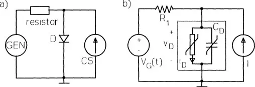
In this section the path from a physical system to prediction of its electrical response is outlined via an extremely simple example shown in Figure 1.1(a). The modeling stage relies on the assignment of certain models to the various devices involved. At this point we have to choose which physical phenomena should be incorporated in the model, and which are to be neglected. In the system shown in Figure 1.1(a) we assume the following models: resistance R1 for the resistor, voltage source VG(t) = 1(t)A sin(ωt) switched on at the instant t = 0 for the a.c. generator GEN, constant current source I for the current supplier CS and, finally, an assembly of nonlinear conductance iD(vD) = is[exp(vD/VT) –1] and nonlinear capacitance CD(vD) = CD0 exp(vD/VT) for the diode D. Thus we have carried out the modeling procedure that results in the circuit in Figure 1.1(b).
The circuit is a mathematical object subject to computer analysis. Before passing to analysis itself, we have to answer three important questions. The first two are whether the accuracy of the models is sufficient for our specific engineering problem, and the whether parameters of the models might be easily identified by an appropriate measuring and fitting procedure. The third question is whether, due to the complexity of the model, the whole circuit is not too large to be solved by the computer available. To our surprise, these problems are neither marginal, nor obvious. In practice, engineers make use of proprietary models as, for example, those implemented in the ubiquitous circuit simulator SPICE [1.1, 1.2, 1.3, 1.4], and often employ measured sets of parameters provided by companies as libraries. They should know, however, that even common device models are sometimes not suitable in certain ranges of signals, and the extraction of parameters by taking measurements in those ranges may involve considerable inaccuracy. Discussion of these important topics is beyond the scope of our book.
Figure 1.1 (a) A simple system and (b) its circuit model
Coming back to our circuit in Figure 1.1(b) we are able to set up its mathematical characterization. Though practical circuits are quite complicated, even such a small example exhibits what is essential in circuit...