eBook - ePub
Aerodynamics of Large Bridges
Proceedings of the First International Symposium on Aerodynamics of Large Bridges, Copenhagen, Denmark, 19-21 February 1992
- 320 pages
- English
- ePUB (mobile friendly)
- Available on iOS & Android
eBook - ePub
Aerodynamics of Large Bridges
Proceedings of the First International Symposium on Aerodynamics of Large Bridges, Copenhagen, Denmark, 19-21 February 1992
About this book
As bridges spans get longer, lighter and more slender, aerodynamic loads become a matter of serious study. This volume of proceedings reflect the co-operation between civil and mechanical engineering and meteorology in this field.
Trusted by 375,005 students
Access to over 1.5 million titles for a fair monthly price.
Study more efficiently using our study tools.
Information
Bridge engineering and aerodynamics
COWI consult, Consulting Engineers and Planners A/S, Denmark
ABSTRACT: Aerodynamic performance of long span bridges is accentuated by the trends to span still wider straits and busy shipping lanes, safely and economically. The present paper outlines the salient aerodynamic features in present and future bridge design. The theoretical and experimental tools available to the designer are addressed. Research and development needs are identified in order to meet the aerodynamic challenges where costs, construction and maintenance will introduce new structural materials with improved strength/weight ratios. Such very light structures will be aerodynamically sensitive if special precautions are not taken. A computer controlled active stabilization system is outlined inspired by active control surface systems in advanced aircraft.
1 INTRODUCTION
The oldest form of bridge used for spanning land or water is probably pure suspension bridges. The earliest examples had cables consisting of jungle creepers or iron chains. This material was used in China already two hundred years BC.
The load was carried by the tension cables acting alone, and the flexible deck had to follow the curve of the cables although it did not always rest directly on them. The purpose of these bridges was to provide a pathway -and it was not always a safe one.
They were highly deformable as the pure tensional members had to deform from the catenary shape in order to carry imposed concentrated load. The much later introduced stiffening girder was an improvement. It stiffens the bridge and distributes concentrated loads along the cable by shear and moments.
The age of the fully developed suspended span with a horizontal traffic path began in the 19th Century. James Finley built some 40 bridges in the first decade. They were quite daring, prone as they were to destruction by relatively light loads – and winds.
For more than 150 years interaction between wind and structure was poorly understood in suspension bridge design. Many suspended spans were damaged or completely wrecked by storm winds. Notable examples recorded by eye witnesses are: Brighton Chain Pier (1836), Menai Straits (1839), Wheeling (1854) and Niagara-Clifton (1888) (Shirly-Smith 1964, Plowden 1974).
The awakening for aerodynamic investigations did not come until the very light and slender Tacoma Narrows Bridge was destroyed by a relatively low 20 m/s wind in 1940 (Farquahrson et. al. 1949).
It was probably the problem of dynamic instability and structure/wind interaction that caused most of the earlier wind-induced failures of suspension bridges as well.
2 DESIGN REQUIREMENTS AND WIND EFFECTS
The challenges for the designer are to develop bridge concepts with sufficient structural reliability and avoid e.g. excessive deformations, cracking, plastic deformation, and of course collapse.
Long service life requires a structure with minimum deterioration and wear: durability.
Likewise, the users require a high level of comfort: serviceability.
The society requires a low level of risk associated with operation of the bridge structures: third party risk.
The aerodynamic phenomena which must be considered with respect to the above criteria can roughly be categorized as follows:
– Aerodynamic instability – statical divergence or flutter – which if allowed to develop, will destroy the bridge.
– Buffeting, the forced movements caused by randomly fluctuating wind loads (turbulent) present at all wind speeds. Buffeting should be limited in order to obtain sufficient reliability and adequate comfort.
– Vortex shedding, including forced vibrations induced in non streamlined objects like buff deck sections.
– Rain induced vibration of cables, caused by change of aerodynamic properties from water flow along the cables.
– Traffic comfort requires low acceleration levels for the structures and limitation of variations of lateral wind loads and wake turbulence on passing vehicles.
3 ELEMENT SHAPES AND CONFIGURATIONS
In long span cable supported bridges all the different structural elements contribute as an assembly to the overall aerodynamic performance. The stiffening girder generates normally the major part of the wind loading. For very long span bridges the towers, cables and equipment also contribute considerably to the overall aerodynamic behaviour of the structure.
3.1 Truss Girders
Historically most long span cable supported bridges have been built with truss girders in order to facilitate fabrication and erection, whereas little attention was paid to maintenance and aerodynamic performance. A notable exception to the latter is the design philosophy proposed by Roebling who suggested truss railings for stiffening the storm-wrecked Wheeling span reconstructed in 1855 (Plowden 1974). Roebling also devised deep timber trusses for the two level Niagara rail and road suspension bridge (1855) which, unlike other suspended spans at the Niagara, survived the frequent storms at this location (Shirly-Smith 1964).
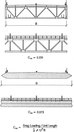
Fig. 3.1 Drag coefficient CD0for a truss section and a streamlined box section (Little Belt suspension bridge).
Trusses can be designed to exhibit sufficient torsional stiffness to safeguard the bridge against torsional flutter instability by introducing horizontal top and bottom windbracings and adopting a truss depth of 1:170 -1:120 of the span length.
The flutter resistance can be further enhanced by longitudinal open slots in the road deck, a well known feature from post World War II suspension bridges in North America and Japan.
The open lattice truss structure perpendicular to the wind also prevents periodic formation and shedding of large vortices in the wake of the truss with associated risk of resonant oscillation.
However, truss sections usually exhibit quite high wind forces (drag loading) which must be resisted by the bridge structure. This will have a relative effect on costs. As an example, figure 3.1 compares the drag coefficient CD0 at zero incidence measured for a truss and box design for the Little Belt bridge (Ostenfeld et. al. 1970). It is noted that the drag of the truss section is more than 3 times that of the streamlined box. The Little Belt bridge was one of the two first suspension bridges adopting the modern box girder design.
The high lateral wind loads for truss girders compared to streamlined box girders are usually only of relative minor importance for medium span classical suspension bridges. It is of fundamental importance in the design of long span cable-stayed bridges, particularly during the cantilever erection, and in the case of very long span suspension bridges.
Truss girders are commonly found to be 15% – 20% heavier than box girders designed for similar live load. Also maintenance is difficult, and costs are considerably higher.
Nevertheless, the truss girder still remains an alternative for future long span bridges -particularly from the point of view of aerodynamic stability. Further development would be useful to minimize structural dead load and drag loading. This may partly be accomplished by use of aerodynamically shaped (circular or – even better – elliptical) members.
3.2 Box Girders
The need for fast and efficient rebuilding of approximately 8500 bridges in post-war Germany called for the development of new design concepts and fabrication techniques. The box girder, originally introduced by Robert Stephenson in the 19th Century, was perfected into the thin-walled all-welded structural member commonly used today (Plowden 1974). Contrary to the traditional truss girder, the orthotropic steel deck in a contemporary box girder serves as an integral part of the structure. Substantial savings in weight are obtained, also in construction and maintenance costs, but aerodynamic problems persist. In particular during the erection phases when the girder lacks the final torsional stiffness, mass and continuity.
Aerodynamically the box section concept holds a promise to reduce the lateral wind loading in comparison with the truss girder, as demonstrated in figure 3.1, while maintaining the structural stiffness in torsion. A drawback is the tendency of the wind to form and shed vortices in the wake of the box because of insufficiently aerodynamical shaping of the downstream edge of the girder. In many instances this leads to small amplitude oscillations at low wind speeds. Vortex induced oscillations may not have immediate catastrophic consequences for the bridge structure itself, but are unacceptable to users, and may cause structural fatigue and wear in joints and bearings. Vortex shedding action can be reduced to an acceptable level by "streamlining" the box section, i.e. use of aerodynamic fairings – guide vanes – at the wind-ward and down-wind edges as used for the first time for the Little Belt bridge (Ostenfeld et. al. 1970). This method has also found its use as a retrofit measure i.e. in case of the Long’s Creek cable-stayed bridge (Wardlaw & Goettler 1968).
In bridge design a set of conflicting requirements becomes apparent in case of the box girder. A slender airfoil shaped bridge girder would produce minimum drag and efficiently prevent vortex shedding. Practical bridge decks with an upper surface suitable for traffic can only with difficulty be shaped with a sufficiently low thickness ratio to obtain minimum drag. Ideally, low thickness ratio (depth/width) should be combined with soft curvatures of panels extended thin trailing edge and rounded upstream nose (airfoil design). For real bridges the deck may be exposed to wind from both sides. Thus a box design, symmetrical about the vertical centre plane and featuring rounded off edges, is preferable. In this case, disadvantageous downstream flow may develop, but can be compensated/improved by introduction of guide vanes.
The aerodynamic instability of box girders is often found to be of the classical flutter type (2 Degree Of Freedom – 2 DOF – bending/torsion) also encountered in aeronautical engineering for the wings of aircraft. Flutter often becomes a governing factor in the design of very long span bridges, and it is conceivable to have catastrophic consequences for the bridge structure, if stability requirements are not observed as for the Tacoma bridge. The aerodynamic stability performance of cross sections may conveniently be compared to that of a flat plate section with identical width and dynamic properties. The critical wind speed Uf for the onset of flutter for a flat plate (which can be determined theoretically) becomes a suitable reference figure for evaluation of the flutter performance of actual bridge section designs. Figure 3.2 shows the critical wind speed relative to that of the flat plate, Uc/Uf, for three box section geometries investigated for the Little Belt suspension bridge (Ostenfeld et. al. 1970). It is observed that by gradually "streamlining" the rectangular box, i.e. by fitting of cantilevered decks or wedge shaped fairings successively, it is possible to more than double the critical wind speed of the proposed box section.
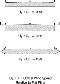
Figure 3.2 Critical wind speeds for three box girder concepts suggested for the Little Belt suspension bridge.
Further enhancement of the critical wind speed Uc can be obtained by longitudinal ventilated slots as known from traditional truss girders. Figure 3.3 shows the critical wind speed relative to that of the flat plate, Uc/Uf for five girder sections intended for suspension bridges with main spans in the range of 2000 m – 3000 m. Two box sections for road bridges are shown along with proposals for two level combined box/truss sections designed for road and rail traffic. It is noted that longitudinal ventilated slots present a means to subdue aerodynamic instability of bridge girder cross sections. The penalty is increased drag – and construction costs.
Judging from figure 3.3 the slotted box section performs approximately 20% better (critical wind speed) than the conventional "streamlined" box. The actual increase in critical wind speed for a given bridge design is somewhat higher due to the increase of torsional stiffness and mass of the slotted box over that of the conventional design. This is illustrated in figure 3.4 which compares critical wind speeds of conventional 3 span suspension bridges with main span lengths from 2000 m – 5000 m based on the slotted and the conventional box girder concept. It is observed that the critical wind speeds obtained for the slotted box girder are enhanced by approximately ...
Table of contents
- Cover
- Half Title
- Title Page
- Copyright Page
- Table of Contents
- Preface
- 1 Overview
- 2 Wind
- 3 Aerodynamic aspects
- 4 Tools
- 5 Application!design
- 6 Great Belt experience
- 7 The future
- Author index
Frequently asked questions
Yes, you can cancel anytime from the Subscription tab in your account settings on the Perlego website. Your subscription will stay active until the end of your current billing period. Learn how to cancel your subscription
No, books cannot be downloaded as external files, such as PDFs, for use outside of Perlego. However, you can download books within the Perlego app for offline reading on mobile or tablet. Learn how to download books offline
Perlego offers two plans: Essential and Complete
- Essential is ideal for learners and professionals who enjoy exploring a wide range of subjects. Access the Essential Library with 800,000+ trusted titles and best-sellers across business, personal growth, and the humanities. Includes unlimited reading time and Standard Read Aloud voice.
- Complete: Perfect for advanced learners and researchers needing full, unrestricted access. Unlock 1.5M+ books across hundreds of subjects, including academic and specialized titles. The Complete Plan also includes advanced features like Premium Read Aloud and Research Assistant.
We are an online textbook subscription service, where you can get access to an entire online library for less than the price of a single book per month. With over 1.5 million books across 990+ topics, we’ve got you covered! Learn about our mission
Look out for the read-aloud symbol on your next book to see if you can listen to it. The read-aloud tool reads text aloud for you, highlighting the text as it is being read. You can pause it, speed it up and slow it down. Learn more about Read Aloud
Yes! You can use the Perlego app on both iOS and Android devices to read anytime, anywhere — even offline. Perfect for commutes or when you’re on the go.
Please note we cannot support devices running on iOS 13 and Android 7 or earlier. Learn more about using the app
Please note we cannot support devices running on iOS 13 and Android 7 or earlier. Learn more about using the app
Yes, you can access Aerodynamics of Large Bridges by Allan Larsen in PDF and/or ePUB format, as well as other popular books in Technology & Engineering & Civil Engineering. We have over 1.5 million books available in our catalogue for you to explore.