- 256 pages
- English
- ePUB (mobile friendly)
- Available on iOS & Android
eBook - ePub
Vector Control of AC Drives
About this book
Alternating current (AC) induction and synchronous machines are frequently used in variable speed drives with applications ranging from computer peripherals, robotics, and machine tools to railway traction, ship propulsion, and rolling mills. The notable impact of vector control of AC drives on most traditional and new technologies, the multitude of practical configurations proposed, and the absence of books treating this subject as a whole with a unified approach were the driving forces behind the creation of this book.
Vector Control of AC Drives examines the remarkable progress achieved worldwide in vector control from its introduction in 1969 to the current technology. The book unifies the treatment of vector control of induction and synchronous motor drives using the concepts of general flux orientation and the feed-forward (indirect) and feedback (direct) voltage and current vector control. The concept of torque vector control is also introduced and applied to all AC motors. AC models for drive applications developed in complex variables (space phasors), both for induction and synchronous motors, are used throughout the book. Numerous practical implementations of vector control are described in considerable detail, followed by representative digital simulations and test results taken from the recent literature.
Vector Control of AC Drives will be a welcome addition to the reference collections of electrical and mechanical engineers involved with machine and system design.
Trusted by 375,005 students
Access to over 1.5 million titles for a fair monthly price.
Study more efficiently using our study tools.
Information
Print ISBN
9780849344084
Chapter 1
INTRODUCTION
1.1 Electric Drives Topology
In the present day technology, electric drives have numerous applications ranging from rudimentary motion control to high-precision machine tools and robotics. A block diagram representation of a modern electric drive is shown in Fig. 1.1. The electric machine is assigned to do a certain mechanical work in terms of operating a load. Trains, rolling mills, paper mills, machine tools, cranes, excavators, elevators, pumps, robots, printers, etc., constitute typical loads on electric drives. Operation of a load is specified in terms of transient or steady torque, speed and/or position response requirements. The electric machine in the drive system should match the load requirements, obviously without exceeding the voltage and current limitations imposed by the machine and the associated power electronics.
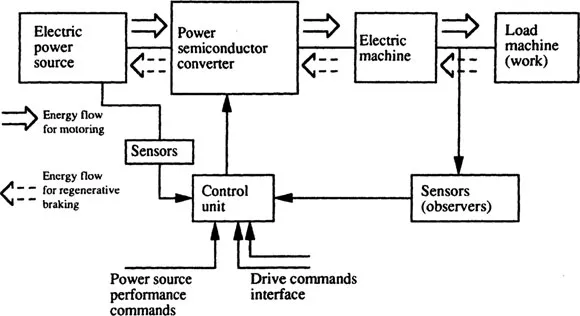
Fig. 1.1 Block diagram of a modern electric drive
Electric machines commonly used in electric drives are: dc commutator, synchronous and induction machines. Synchronous and induction machines are characterized by rotating (or traveling) airgap fields produced by ac mmfs. Thus, in contrast to dc commutator machines which have space-stationary trapezoidally distributed fields, ac synchronous and induction machines have sinusoidally distributed (ideally) traveling fields and have no commutators. In this text we treat only traveling field machines and term the associated drives as ac drives.
Referring again to the block diagram of Fig. 1.1, the power semiconductor converter controls the flow of electric power between the motor and the power source such that the motor matches the load requirements. The converter is an electric power conditioner and acts as a voltage and frequency changer. As the electric machine is a bilateral (that is, reversible) device, the flow of power in an electric drive should be bi-directional — from the electric power source to the load during motoring, and from the load to the source during regenerative braking. As depicted in Fig. 1.2, the flow of power in an electric drive involves an energy conversion process accompanied by losses. Loss and cost minimizations are two almost conflicting goals in the design and optimization of electric drives.
The control of the converter to match the load requirements with motor capabilities is built in the low-voltage, low-power control unit. The control unit consists of linear and digital integrated circuits and transistors or digital signal processors (DSPs). The command interfaces (Fig. 1.1) the inputs to the control unit which, in order to adjust the operating point (torque, speed or position) of the drive, makes use of direct feedback sensors, or indirect observers of some of the state variables such as voltages, fluxes, currents, torque, speed, and position. The sensors and/or observers are also used for motor-converter protection.
In order to reduce the converter harmonics pollution in the electric power source and to control the power factor at the source, separate sensors are required to measure voltages and currents of the power source. The control unit, based on separate commands (unity power factor) and sensors, then produces the required performance on the power source side (Fig. 1.1). In general, a dual converter — one on the power source side and one on the motor side with a dc voltage or current link — is required to provide both drive control and power source performance requirements.
We now discuss motor loads, converters, performance indices and controllers.
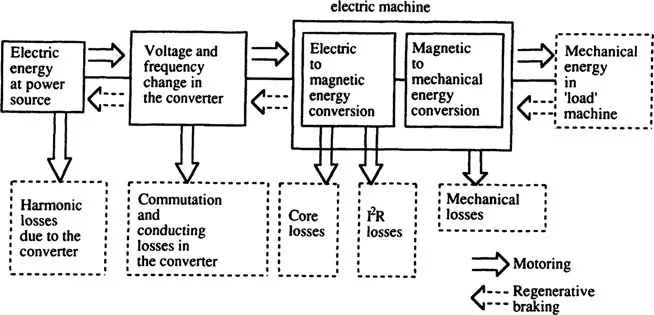
Fig. 1.2 Energy conversion and losses in an electric drive for motoring and regenerative braking modes
1.2 Motor Load Dynamics and Stability
Generally, the load on the motor of an electric drive is coupled through a mechanical transmission characterized by speed multiplication (or division) ratio, elasticity, and backlash [1]. For the present, let us consider the load as an equivalent rotational system shown in Fig. 1.3, with a rigid shaft coupling to the motor and having a lumped moment of inertia J. With the rotational speed Ωr and the rotor position θr, the following equations hold:
(1.1) |
and
(1.2) |
where Te=electromagnetic torque and TL = load torque, including mechanical rotational losses. Under steady-state, Te=TL. For ac traveling field machines, we use ωr instead of Ωr, where ωr is the rotor speed in electrical radians per second and
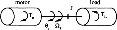
Fig. 1.3 Electric drive with rigid shaft coupling
(1.3) |
P being the number of pole-pairs. Similarly, for the rotor position in electrical degrees, θer, we have
(1.4) |
The components of the total load torqu...
Table of contents
- Cover
- Half Title
- Title Page
- Copyright Page
- Table of Contents
- Preface
- CHAPTER 1. INTRODUCTION
- CHAPTER 2. AC MOTOR MODELS FOR DRIVE APPLICATIONS
- CHAPTER 3. FUNDAMENTALS OF INDUCTION MOTOR VECTOR CONTROL
- CHAPTER 4. VECTOR CONTROL OF VOLTAGE-SOURCE INVERTER-FED INDUCTION MOTOR DRIVES
- CHAPTER 5. VECTOR CONTROL OF CURRENT-SOURCE INVERTER-FED INDUCTION MOTOR DRIVES
- CHAPTER 6. VECTOR CONTROL OF SYNCHRONOUS MACHINES
- CHAPTER 7. VECTOR CONTROL OF PERMANENT MAGNET SYNCHRONOUS MOTOR DRIVES
- CHAPTER 8. VOLTAGE CONTROL OF VOLTAGE-SOURCE INVERTED-FED RELUCTANCE SYNCHRONOUS MOTOR DRIVES
- CHAPTER 9. VECTOR CONTROL OF CYCLOCONVERTER-FED SYNCHRONOUS MOTOR DRIVES
- CHAPTER 10. VECTOR CONTROL OF CURRENT-SOURCE INVERTER-FED MOTOR DRIVES
- Index
Frequently asked questions
Yes, you can cancel anytime from the Subscription tab in your account settings on the Perlego website. Your subscription will stay active until the end of your current billing period. Learn how to cancel your subscription
No, books cannot be downloaded as external files, such as PDFs, for use outside of Perlego. However, you can download books within the Perlego app for offline reading on mobile or tablet. Learn how to download books offline
Perlego offers two plans: Essential and Complete
- Essential is ideal for learners and professionals who enjoy exploring a wide range of subjects. Access the Essential Library with 800,000+ trusted titles and best-sellers across business, personal growth, and the humanities. Includes unlimited reading time and Standard Read Aloud voice.
- Complete: Perfect for advanced learners and researchers needing full, unrestricted access. Unlock 1.5M+ books across hundreds of subjects, including academic and specialized titles. The Complete Plan also includes advanced features like Premium Read Aloud and Research Assistant.
We are an online textbook subscription service, where you can get access to an entire online library for less than the price of a single book per month. With over 1.5 million books across 990+ topics, we’ve got you covered! Learn about our mission
Look out for the read-aloud symbol on your next book to see if you can listen to it. The read-aloud tool reads text aloud for you, highlighting the text as it is being read. You can pause it, speed it up and slow it down. Learn more about Read Aloud
Yes! You can use the Perlego app on both iOS and Android devices to read anytime, anywhere — even offline. Perfect for commutes or when you’re on the go.
Please note we cannot support devices running on iOS 13 and Android 7 or earlier. Learn more about using the app
Please note we cannot support devices running on iOS 13 and Android 7 or earlier. Learn more about using the app
Yes, you can access Vector Control of AC Drives by Ion Boldea,Syed A. Nasar in PDF and/or ePUB format. We have over 1.5 million books available in our catalogue for you to explore.