eBook - ePub
Geotechnical Engineering for Transportation Infrastructure
- 158 pages
- English
- ePUB (mobile friendly)
- Available on iOS & Android
eBook - ePub
Geotechnical Engineering for Transportation Infrastructure
About this book
This volume provides an overview of the proceedings of the XIIth ECSME Conference 1999. It covers a wide variety of topics, from summaries of workshops and sessions, to the emergence of information technology and information retrieval and communication.
Trusted by 375,005 students
Access to over 1.5 million titles for a fair monthly price.
Study more efficiently using our study tools.
Information
Information technology in the geotechnical profession
Full papers of workshop 4
Validation of computer programs in geotechnical design
Geocentrix Ltd, Banstead, Surrey, UK
Keywords: software, validation, modelling
ABSTRACT: The Paper discusses what can be done to counter perceived problems of using computer technology for design. It describes the four key components of today’s electronic offices: people, software, hardware, and process. The distinction between engineering, conceptual, and computational models is discussed.
1 INTRODUCTION
“Information technology is providing greatly increased power to generate and transfer information … [but] safeguards are needed to ensure competent use of [this] generated material” (11th Report of SCOSS 1997)
The main worries are (10th Report of SCOSS 1995):
– Users with inadequate engineering knowledge,
– Communication gaps between the engineer and the software developer,
– Programs being used out of context,
– Checking processes that are not sufficiently fundamental,
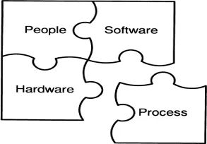
Figure 1. Key components of today’s electronic office.
– A program’s limitations may not be apparent,
– Programs dealing with unusual structures are particularly weak.
This paper looks at the four key components of today’s electronic office (see Figure 1), in an attempt to identify what can be done to alleviate these concerns.
2 SOFTWARE
ISO 9126:1991 defines six characteristics that describe software quality. These are (see Figure 2):
– Functionality – can the software do what is required?
– Reliability – is it well tried and tested?
– Usability – can it be used effectively without significant error?
– Efficiency – does it need excessive computer resources?
– Maintainability – can it be updated if necessary?
– Portability – can it be run on several computers?
The relative importance of the six quality characteristics is indicated by size of each ‘stone’ in the pyramid of Figure 2.
ISO 9126 recommends evaluating software on a scale of excellent to poor in all of the categories described above (where relevant). Since the fitness of a computer program for a particular purpose depends on that purpose, no general rating levels can be given but should be defined for each specific evaluation.
2.1 Hardware
Software cannot run effectively without the proper hardware:
– Suitable input devices must be available (e.g. keyboard, mouse, digitizer, scanner, microphone, etc.);
– The means of transferring data from other electronic devices must be available (e.g. floppy-disk, CD-ROM, tape, Internet connection, etc.);
– Network connections (if used) must be adequate (e.g. rate of data transfer, capacity of storage media, etc.);
– Suitable output devices must be available (e.g. printer, floppy-disk, CD-ROM, tape, Internet connection, etc.);
– Adequate backup facilities must exist (floppy-disk, CD-W, tape, ZIP-drive, etc).
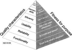
Figure 2. Pyramid of virtues for engineering software.
3 PEOPLE
People are at the heart of the electronic office. The roles played by members of a computer-based project team are illustrated in Figure 3. In a large office, each role in the computer-based project team would be assigned to a different person: in a small office, some roles are combined.
The technical manager of a computer-based project team is responsible for planning the work, obtaining the necessary equipment (hardware and software), and reviewing the outcome. He should be a chartered engineer with sufficient expertise to assess and take responsibility for the overall fitness-for-purpose of the team’s work.
The analyst’s role within this team is to develop models, run analyses, and to check the results of his work. The qualifications and experience needed by an analyst depend to a great extent on the complexity and usability of the software. Proper training of analysts is essential to ensure their competence, but training is not in itself sufficient – experience also counts for a lot.
The person responsible for checking the results of the modelling exercise should not be the analyst. Successful modelling relies on an independent check of the work being performed either in-house (for example, by a senior engineer) or externally (for example, by a checking agency). On many projects the technical manager also serves as the checker.
Finally, a software specialist is often needed to assist in the selection of suitable software and to run the analyses. The software specialist may be someone from within the organization performing the analysis or an external consultant (possibly an employee of the software vendor).
Each person assigned to a task within the computer-based project team should have sufficient skill and experience to check his work for fitness-for-purpose. In this context, the work is fit-for-purpose if it accurately, adequately, and reliably meets the acceptance criteria previously established for it (see the later discussion of acceptance criteria).
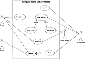
Figure 3. Roles played by members of a computer-based project team (UML use-case diagram).
4 PROCESS
Modelling an engineering structure involves five separate activities, as shown on Figure 4.
– In the planning phase, the engineer decides what the purpose of the modelling exercise is, for example:
– To demonstrate that a footing has an adequate factor of safety against excessive settlement;
– To predict the short- and long-term deformation of an embedded retaining wall;
– To estimate the rate of flow of water through an earth dam.
Once the purpose of the exercise has been determined, the engineer produces models of the engineering system, capturing those features of the structure and its surrounds that are relevant to the subsequent analysis.
As a parallel activity, the equipment (hardware and software) needed to study the model is obtained, providing the means for the engineer to perform whatever calculations are necessary to answer the questions posed during the planning phase.
Finally, the engineer reviews the outcome of the modelling exercise and decides whether to accept them as fit for purpose or to reject them - in which case he may revise some aspect of the modelling exercise before re-running the calculations.
The remainder of this paper describes in detail the various activities in the modelling process shown in Figure 4.
The process of modelling an engineering structure involves the construction of a variety of models, including:
– An engineering model
– One or more conceptual models
– One or more computational models
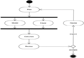
Figure 4. Overview of the modelling process (UML activity diagram).
The engineering model is a definition of the physical entity (as exists or as planned) that will be studied in the modelling exercise. The engineering model should be designed to meet the purpose of the modelling exercise. Several different engineering models may be needed to capture the full behaviour of an engineering structure.
A conceptual model is a simplified form of the engineering model, which omits physical features that have no significant effect on the aspect of the system being studied. In order to obtain an analytical solution, it may also omit features which are significant.
A computational model is a model that allows a solution to the conceptual model to be obtained. Different models are needed for different computer programs.
4.1 Example of different models
Figure 5 illustrates the difference between the engineering model of a slope and possible conceptual and computational models for it. The conceptual models (left, circular slip surface; and right, two-part wedge mechanism) capture the physical characteristics of the engineering system and the method of analysing it.
Two possible computational models are shown in Figure 5 for the circular slip mechanisms: one using a smaller slice width than the other. Typically, an analyst would perform a parametric study to determine whether the coarser model (coarser model sacrifices resolution for computational speed) is fit for its intended purpose.
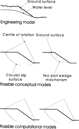
Figure 5. Engineering, conceptual, and computational models for a slope.
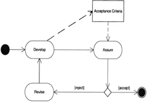
Figure 6. Acceptance criteria act as the link between model development and model assurance (UML activity diagram).
In practice, an analyst would strive to limit the number of models needed to study a particular conceptual model. An example of when more than one computational model is used is to study the influence of mesh size and shape in a finite element analysis.
4.2 Acceptance criteria
Developing models involves two complementary activities:
– Development itself (i.e. creation of the model);
– Assurance (i.e. checking the model).
Acceptance criteria are used to check that the model is fit for its purpose and should be established as a by-product of the development activity, before proceeding to assurance (see Figure 6).
By making the establishment of acceptance criteria a distinct action, attention is focussed on creating effective tests of the proposed model.
5 CONCLUSIONS
Successful modelling of engineering structures depends on several factors, not least of which...
Table of contents
- Cover
- Half Title
- Title Page
- Copyright Page
- Table of Contents
- Reflection on the Conference Consideration and Justification
- Recapitulation of the Conference Summaries of Sessions, Workshops and Specials
- Information technology in the geotechnical profession Full Papers of Workshop 4
- Miscellaneous
Frequently asked questions
Yes, you can cancel anytime from the Subscription tab in your account settings on the Perlego website. Your subscription will stay active until the end of your current billing period. Learn how to cancel your subscription
No, books cannot be downloaded as external files, such as PDFs, for use outside of Perlego. However, you can download books within the Perlego app for offline reading on mobile or tablet. Learn how to download books offline
Perlego offers two plans: Essential and Complete
- Essential is ideal for learners and professionals who enjoy exploring a wide range of subjects. Access the Essential Library with 800,000+ trusted titles and best-sellers across business, personal growth, and the humanities. Includes unlimited reading time and Standard Read Aloud voice.
- Complete: Perfect for advanced learners and researchers needing full, unrestricted access. Unlock 1.5M+ books across hundreds of subjects, including academic and specialized titles. The Complete Plan also includes advanced features like Premium Read Aloud and Research Assistant.
We are an online textbook subscription service, where you can get access to an entire online library for less than the price of a single book per month. With over 1.5 million books across 990+ topics, we’ve got you covered! Learn about our mission
Look out for the read-aloud symbol on your next book to see if you can listen to it. The read-aloud tool reads text aloud for you, highlighting the text as it is being read. You can pause it, speed it up and slow it down. Learn more about Read Aloud
Yes! You can use the Perlego app on both iOS and Android devices to read anytime, anywhere — even offline. Perfect for commutes or when you’re on the go.
Please note we cannot support devices running on iOS 13 and Android 7 or earlier. Learn more about using the app
Please note we cannot support devices running on iOS 13 and Android 7 or earlier. Learn more about using the app
Yes, you can access Geotechnical Engineering for Transportation Infrastructure by F.B.J. Barends,J. Lindenberg,H.J. Luger,A. Verruijt,L. de Quelerij in PDF and/or ePUB format, as well as other popular books in Technology & Engineering & Civil Engineering. We have over 1.5 million books available in our catalogue for you to explore.