eBook - ePub
Experimental Techniques and Design in Composite Materials
Proceedings of the 4h Seminar, Sheffield, 1-2 September 1998
- 174 pages
- English
- ePUB (mobile friendly)
- Available on iOS & Android
eBook - ePub
Experimental Techniques and Design in Composite Materials
Proceedings of the 4h Seminar, Sheffield, 1-2 September 1998
About this book
This volume contains the revised versions of papers presented at the 4th Seminar on Experimental Techniques and Design in Composite Materials. The papers have been divided into five sections: fatigue, test methods, design, impact and modelling.
Trusted by 375,005 students
Access to over 1.5 million titles for a fair monthly price.
Study more efficiently using our study tools.
Information
Subtopic
Civil EngineeringGuidelines for fatigue design of fibre-reinforced metal matrix composites
University of Sheffield - Department of Mechanical Engineering Mappin Street, Sheffield S1 3JD U.K.
ABSTRACT: Composite Fracture Mechanics principles are used to model fatigue crack growth in MMCs. In its simplest form composite modelling considers the material as a composite of two components, matrix and fibre, with a crack system divided into three zones: the crack, the plastic zone and the fibre constraint zone. The solution of the model equations allows for the calculation of the stresses sustained by the crack wake, plastic zone, barrier zone and elastic enclave. It also leads to the calculation of the crack open displacement (COD) over the entire crack length and of the crack tip open displacement (CTOD). Crack growth rate is calculated through a Paris type relationship in terms of CTOD, i.e. da / dN = C × CTODm. Conditions for crack arrest and instability are established and used to derive fundamental tools for damage tolerance design.
1 INTRODUCTION
Composite Fracture Mechanics is a spin-off of Microstructural Fracture Mechanics which deals with fracture problems where the microstructure of the material plays a significant part. One significant area is the study of short fatigue cracks in which important developments have taken place in the past few years.
These developments have demonstrated the considerable effect that a materials microstructure has on the early stages of crack growth (Miller 1987), and have introduced the concept of microstructural barriers to crack propagation and their connection with the fatigue limit (de los Rios et al. 1984 & 1985). Work in this area has also demonstrated the importance of crack tip plastic deformation in the crack propagation rate (Chang et al. 1979, Weertman 1966).
The understanding of these two aspects i.e. barrier strength and crack tip plasticity, and their influence on crack growth, has led to the evolution of short crack models from an empirical beginning (Hobson et al. 1986) to a more fundamental approach (Navarro & de los Rios 1988a). It is now possible to incorporate the mechanical driving force of crack growth, represented by the applied stress and crack length, and the material resistance in a explicit form within the crack system equations (Navarro & de los Rios 1992, de los Rios et al. 1994).
The material resistance is of two kinds, one is intrinsic and considers the material parameters controlling crack tip plastic flow such as those which determine the strength of the barriers such as the differential strength of constituent phases and the transfer of plasticity across barriers. The other resistance encountered as the crack grows concerns the interaction between the crack faces such as crack locking or bridging and is a function of both the friction forces on the faces, which is dominated by crack surface topography, and Mode I crack tip plasticity, which controls crack face separation.
2 MICRO-MECHANICAL MODELLING OF CRACK GROWTH
The model crack system is composed of three zones, the crack, the plastic zone and the fibre constraint zone. These three zones are simulated by distribution of dislocations as modelled by Bilby, Cottrel and Swinden (Bilby et al. 1963). The distribution is of screw dislocations for Mode III loading, edge dislocations with the Burger’s Vector parallel to the crack plane for Mode II and edge dislocations with the vector perpendicular to the crack plane for Mode I loading. Navarro and de los Rios have solved the equilibrium equation for a multizone crack system (Navarro & de los Rios 1988b) and applied it to the three zone case (Navarro & de los Rios 1988c).
When the model is applied to fibre-reinforced MMCs (de los Rios et al. 1996a & 1996b) it considers a fatigue crack in a composite of interfibre spacing D and fibre diameter d with the crack tip plastic zone being blocked at the fibre zone (see Fig. 1). The solution of the equilibrium equation provides the means of calculating the distribution of stresses over the three zones; which are σ1 at the crack, σ2 at the plastic zone and σ3 at the fibre constraint zone; (see Fig. 2) and the expression for the crack open displacement, COD. The stress σ1 is the bridging stress, σ2 is the yield stress of the plastic zone and σ3 is calculated as:
(1) |
and the crack open displacement as:
(2) |
where σ is the applied stress; b the Burgers vector, A = Gb/2π for screw dislocations, A=Gb/2π (l-υ) for edge dislocations, υ Poisson’s ratio and G the shear modulus. The other variables are defined in Fig. 1.
If crack growth rate is considered to be a function of crack tip open displacement, CTOD, through a Paris type relationship (see equation 3), then equation (2) determines da/dN when ζa = n1 and ζb = 1.
At critical crack lengths in each interfibre spacing, σ3 attains the value required to overcome the next fibre constraint, plasticity then spreads to the next fibre and the crack is able to propagate through the fibre zone. Alternatively, if the applied stress is below a critical value (endurance limit), then σ3 will not attain the value required to overcome the fibre constraint and the crack arrests. Because crack tip plastic displacement is proportional to the extent of plasticity at the crack tip, it shows an oscillating variation within each fibre spacing. When a barrier is overcome, its value is high, but as the crack grows towards the next fibre, its value decreases to a minimum at the critical crack length (see Fig. (3)).
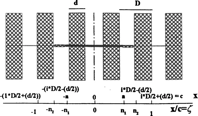
Figure 1. Schematic representation of the crack system. The crack length is 2a, the fibre diameter is d and the fibre spacing is D. On the positive coordinates side the crack tip is at a, the plastic zone extends to the next fibre at i × D/2 - (d/2) and the constrained zone extends to i × D/2 + (d/2), i = 1, 3, 5 …
2.1 Crack propagation rate
Crack propagation rate is calculated by a Paris type relationship using the crack tip open displacement as the driving force:
(3) |
The scale parameters C and m are obtained by a numerical 5method relating the integration of equation (3) between initial and final crack length and the S-N curve of the matrix or by using long crack propagation data and CTOD values corresponding to cracks longer than 6-8 interfibre spacings, which would be beyond the fibre constraint sensitive region of crack growth.
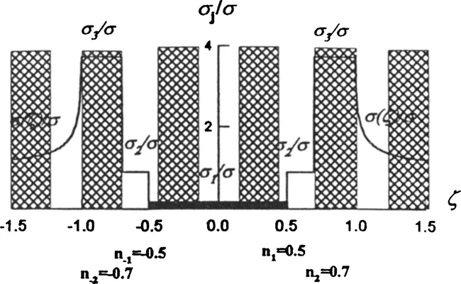
Figure 2. Stress distribution along the crack system. The stress at the crack itself is σ1 (bridging stress), the stress at the plastic zone is the flow stress σ2, the stress at the constrained zone is σ3 and σ(ζ) is the elastic stress distribution.
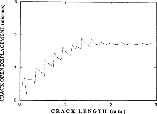
Figure 3. Variation of crack tip open displacement for a propagating crack, showing the effect of fibre constraint at short crack lengths (less than 2 mm) and the negligible effect of fibre constraint at longer crack lengths.
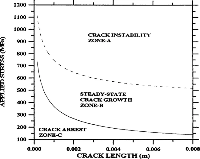
Figure 4. Fatigu...
Table of contents
- Cover
- Half Title
- Title Page
- Copyright Page
- Table of Contents
- Preface
- Section 1: Fatigue
- Section 2: Test Methods
- Section 3: Design
- Section 4: Impact
- Section 5: Modelling
- Author Index
Frequently asked questions
Yes, you can cancel anytime from the Subscription tab in your account settings on the Perlego website. Your subscription will stay active until the end of your current billing period. Learn how to cancel your subscription
No, books cannot be downloaded as external files, such as PDFs, for use outside of Perlego. However, you can download books within the Perlego app for offline reading on mobile or tablet. Learn how to download books offline
Perlego offers two plans: Essential and Complete
- Essential is ideal for learners and professionals who enjoy exploring a wide range of subjects. Access the Essential Library with 800,000+ trusted titles and best-sellers across business, personal growth, and the humanities. Includes unlimited reading time and Standard Read Aloud voice.
- Complete: Perfect for advanced learners and researchers needing full, unrestricted access. Unlock 1.5M+ books across hundreds of subjects, including academic and specialized titles. The Complete Plan also includes advanced features like Premium Read Aloud and Research Assistant.
We are an online textbook subscription service, where you can get access to an entire online library for less than the price of a single book per month. With over 1.5 million books across 990+ topics, we’ve got you covered! Learn about our mission
Look out for the read-aloud symbol on your next book to see if you can listen to it. The read-aloud tool reads text aloud for you, highlighting the text as it is being read. You can pause it, speed it up and slow it down. Learn more about Read Aloud
Yes! You can use the Perlego app on both iOS and Android devices to read anytime, anywhere — even offline. Perfect for commutes or when you’re on the go.
Please note we cannot support devices running on iOS 13 and Android 7 or earlier. Learn more about using the app
Please note we cannot support devices running on iOS 13 and Android 7 or earlier. Learn more about using the app
Yes, you can access Experimental Techniques and Design in Composite Materials by M.S. Found in PDF and/or ePUB format, as well as other popular books in Technology & Engineering & Civil Engineering. We have over 1.5 million books available in our catalogue for you to explore.