- 374 pages
- English
- ePUB (mobile friendly)
- Available on iOS & Android
eBook - ePub
About this book
"Covering virtually all areas of distribution engineering, this complete reference work examines the unique behavior of utilities and provides the practical knowledge necessary to solve real-world distribution problems. "
Trusted by 375,005 students
Access to over 1.5 million titles for a fair monthly price.
Study more efficiently using our study tools.
Information
1
UTILITY DISTRIBUTION SYSTEM DESIGN AND CHARACTERISTICS
Introduction
The distribution engineer sometimes finds it difficult to define a typical distribution system. It is the purpose of this chapter to suggest typical values of voltage, line lengths, load and fault levels, as well as types of system design and grounding which can be used as background information for the more technical discussions later on in the book.
Design
The Utility System
The electric utility system is usually divided into three segments which are generation, transmission, and distribution. A fourth division, which can sometimes be made is subtransmission, which can really be considered a subset of transmission since the voltage levels overlap and operational and protection practices are quite similar. Figure 1-1, shown below, illustrates some of the major components in these divisions.
The distribution system, which is our main area of interest, is commonly broken down into the following three components:
- Distribution substation
- Distribution primary
- Secondary
Even on this greatly simplified one-line diagram, it can be seen that the distribution system consists of a much wider variety of voltage levels, components, loads and interconnections than does the generation or transmission system.
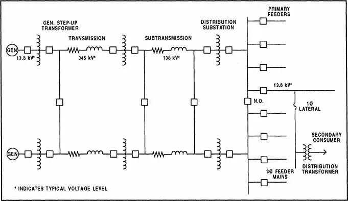
Figure 1-1 Typical Electric Supply System
Distribution Substation
The distribution system is fed through distribution substations. These substations consist of an almost infinite number of designs based on considerations such as
- Load density
- High side voltage
- Low side voltage
- Land availability
- Reliability requirements
- Load growth
- Voltage drop
- Emergency conditions
- Cost and losses
A typical substation is shown in Figure 1-2. This substation indicates the average arrangement and equipment ratings per an industry survey. For example, the voltage of the high side bus can be anywhere from 34.5 kV all the way up to 345 kV and beyond. The average or preferred high side voltage level is approximately 115 to 138 kV because this voltage level is usually high enough to maintain a “stiff” enough source and low enough to alleviate the costs associated with high side equipments. As shown, the average substation consists of two transformers rated 21/28/35 MVA (OA/FA/FOA) with an impedance of approximately 10 percent. Protection of the substation transformer is usually attained via high side breakers or circuit switchers and low side breakers used in conjunction with differential relays (overcurrent relaying is also used as backup and is not shown). The transformer low side breaker, sometimes referred to as the “substation secondary breaker”, is also used to protect against low voltage bus faults as well as back up the feeder breakers.
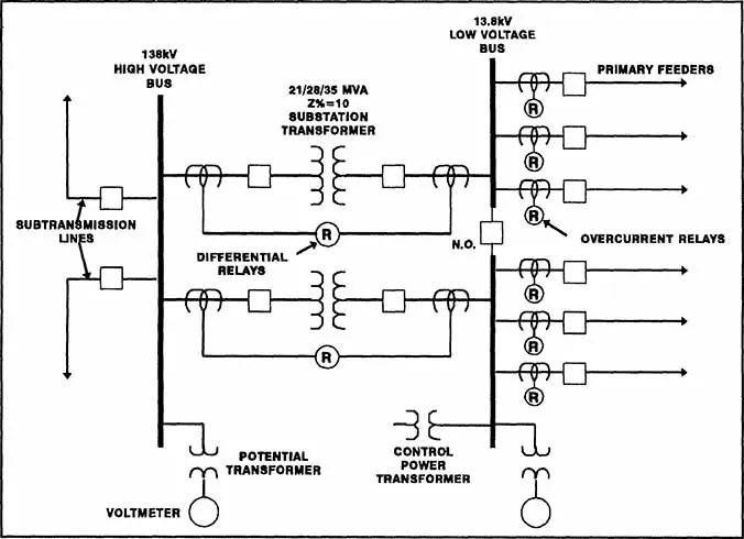
Figure 1-2 Average Distribution Substation Arrangement
The low voltage bus in a multiple transformer substation is usually split (contains a normally open breaker or switch) to alleviate circulating currents as well as reduce the short circuit current seen by the system. Two or more feeders are normally connected to each bus through a feeder breaker. On smaller substations where short circuit levels are lower, a recloser is sometimes used instead of a breaker. Short circuit levels at the terminals of the low voltage bus are generally kept at 12,000 amperes or less although there are many systems where much higher levels can be found.
Distribution Feeders
Figure 1-3 shows a primary distribution feeder with various equipment such as fuses, distribution transformers, reclosers, and switches connected to it. Much of this equipment, such as a recloser, is utilized only at the distribution level. On the other hand, some of the equipment such as capacitors, transformers, and arresters is also used at the transmission levels but with considerably different rules of application. As shown, most distribution feeders are 3-phase and 4-wire. The fourth wire is the neutral wire which is connected to the pole, usually below the phase wires, and grounded periodically.
A three-phase feeder main can be fairly short, on the order of a mile or two, or it can be as long as 30 miles. Voltage levels can be as high as 34.5 kV, with the most common voltages being in the 15 kV class. While most of the 3-phase mains are overhead, much of the new construction, particularly the single-phase lateral construction, is being put underground. Underground systems have the advantage of immunity from certain types of temporary fault conditions like wind, direct lightning strikes, animals, etc. Permanent faults, on the other hand, are much more difficult to locate and repair and have been the subject of much concern in recent years.
There are various feeder designs which can increase customer service. Five of these are shown below in Figure 1-4. These designs are described as follows:
Radial System. It is obvious that the radial system is exposed to many interruption possibilities, the most important of which are those due to primary overhead or underground cable failure or transformer failure. Either event may be accompanied by a long interruption, given nominally by some utilities as 10 to 12 hours. Both components have finite failure rates and such interruptions are expected and statistically predictable. The system will be satisfactory only if the interruptions frequency is very low and if there are ways to operate the system without planned outages. Feeder breakers reclosing or temporary faults may affect sensitive loads.
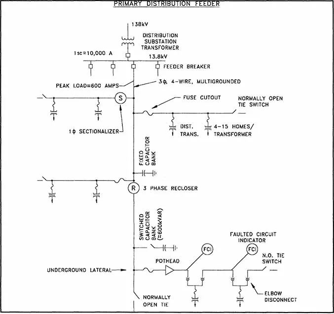
Figure 1-3 Primary Distribution Feeder
Primary Loop. A great improvement is obtained by arranging a primary loop, which provides two-way feed at each transformer. In this manner, any section of the primary can be isolated, without interruption, and primary faults are reduced in duration to the time required to locate a fault and do the necessary switching to restore service. This procedure can be performed either manually or automatically. The cable in each half of the loop must have capacity enough to carry all the load. The additional cable exposure will tend to increase the frequency of faults, but not necessarily the faults per customer. The addition of a loop tie switch at the open point also introduces the possibility of a single equipment fault causing an interruption to both halves of the loop. Murphy’s Law generally applies to these situations. Once again, sensitive loads would be affected by reclosing under temporary fault conditions.
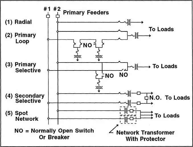
Figure 1-4 Five Basic Service Systems
Primary Selective. This system uses the same basic components as in the primary loop, but arranged in a dual or main/alternative scheme. Each transformer can “select” its source, and automatic switching is frequently used. When automatic, the interruption duration can be limited to two or three seconds. Each service now represents a potential two-feeder outage (if the open switch fails), but under normal contingencies, service restoration is rapid and there is no need to locate the fault (as with the loop) prior to doing the switching. This scheme is in popular use on many underground systems. It also offers little remedy for computer problems caused by temporary faults to the overhead system.
Secondary Selective. This is the first of the service systems using two transformers and low voltage switching. It is not in popular use by utilities for 480 volt service, but is common in industrial plants and on institutional properties. Primary operational switching is eliminated and with it some causes of difficulty. Duplicate transformers virtually eliminate the possibility of a long interruption due to failure. Load is divided between the two units and automatic transfer is employed on loss of voltage to either load. There must be close coordination of utility and customer during planned transfers, and the split responsibility is probably the principal reason for its limited use as a service system. Temporary faults on the primary feeders should have little if any effect on even sensitive computer loads.
Secondary Spot Network. Maximum service reliability and operating flexibility are obtained by use of the spot network using two or more transformer/protector units in parallel. The low voltage bus is continuously energized by all units, and automatic disconnection of any unit is obtained by sensitive reverse power relays in the protector. Maintenance switching of primary feeders can be done without customer interruption or involvement. Spot networks are...
Table of contents
- Cover Page
- Half title
- title
- copy
- dedication
- PREFACE
- 1 UTILITY DISTRIBUTION SYSTEM DESIGN AND CHARACTERISTICS
- 2 TRANSFORMERS AND REGULATORS
- 3 APPLICATION OF CAPACITORS FOR DISTRIBUTION SYSTEMS
- 4 DISTRIBUTION OVERCURRENT PROTECTION
- 5 SURGE ARRESTERS
- 6 DISTRIBUTION RELIABILITY
- 7 POWER QUALITY FUNDAMENTALS
- 8 DISTRIBUTION ECONOMICS
- INDEX
Frequently asked questions
Yes, you can cancel anytime from the Subscription tab in your account settings on the Perlego website. Your subscription will stay active until the end of your current billing period. Learn how to cancel your subscription
No, books cannot be downloaded as external files, such as PDFs, for use outside of Perlego. However, you can download books within the Perlego app for offline reading on mobile or tablet. Learn how to download books offline
Perlego offers two plans: Essential and Complete
- Essential is ideal for learners and professionals who enjoy exploring a wide range of subjects. Access the Essential Library with 800,000+ trusted titles and best-sellers across business, personal growth, and the humanities. Includes unlimited reading time and Standard Read Aloud voice.
- Complete: Perfect for advanced learners and researchers needing full, unrestricted access. Unlock 1.5M+ books across hundreds of subjects, including academic and specialized titles. The Complete Plan also includes advanced features like Premium Read Aloud and Research Assistant.
We are an online textbook subscription service, where you can get access to an entire online library for less than the price of a single book per month. With over 1.5 million books across 990+ topics, we’ve got you covered! Learn about our mission
Look out for the read-aloud symbol on your next book to see if you can listen to it. The read-aloud tool reads text aloud for you, highlighting the text as it is being read. You can pause it, speed it up and slow it down. Learn more about Read Aloud
Yes! You can use the Perlego app on both iOS and Android devices to read anytime, anywhere — even offline. Perfect for commutes or when you’re on the go.
Please note we cannot support devices running on iOS 13 and Android 7 or earlier. Learn more about using the app
Please note we cannot support devices running on iOS 13 and Android 7 or earlier. Learn more about using the app
Yes, you can access Power Distribution Engineering by James J. Burke in PDF and/or ePUB format, as well as other popular books in Technology & Engineering & Electrical Engineering & Telecommunications. We have over 1.5 million books available in our catalogue for you to explore.