![]()
1
Opto-Mechanical Design Process
Paul R. Yoder, Jr., David M. Stubbs, Kevin A. Sawyer, and David Aikens
CONTENTS
1.1 Introduction and Summary
1.2 Establishing the Requirement
1.3 Conceptualization
1.4 Performance Specifications and Design Constraints
1.5 Preliminary Design
1.6 Design Analysis and Computer Modeling
1.7 Error Budgets and Tolerances
1.8 Experimental Modeling
1.9 Finalizing the Design
1.10 Design Reviews
1.11 Manufacturing the Instrument
1.12 Evaluating the End Product
1.13 Documenting the Design
1.14 Systems and Concurrent Engineering
References
1.1 Introduction and Summary
Opto-mechanical design of optical instruments is a tightly integrated process involving many technical disciplines. It begins when the requirement for a particular hardware item is established by the potential user, such as military, other governmental organizations, or commercial representatives who seek ways to expand sales with a new or improved product. Once approved, funded, and staffed, the design effort proceeds through a logical sequence of major steps and concludes only when the instrument is awarded a pedigree establishing its ability to meet all its technical specifications and capable of being produced, within cost limits, in the required quantity—whether that is as a one off (such as the highly successful Hubble Space Telescope [HST]) or as a large number of a much simpler item (such as a new spotting scope with an integral digital camera for nature study).
In this chapter, we treat each major design step in a separate section. Admittedly, our approach is idealized since few designs develop as smoothly as planned. We endeavor to show how the process should occur and trust that those planning, executing, reviewing, and approving the design will have the ingenuity and resourcefulness to cope with the inevitable problems and bring errant design activities into harmony with minimal effect on schedule and cost.
Driving forces behind the methodology applied in the design process include schedule constraints; availability of properly trained personnel; facilities, equipment, and other resources; perceived demands from the marketplace; and the inherent costs of accomplishing and proving the success of the design. These we consider to lie within the province of project management, a subject clearly beyond the scope of this book.
A great influence on the opto-mechanical design process is the degree of maturity of the technology to be applied. For example, not many years ago, the design of the 2.4 m (94.5 in.) aperture HST capable of being lifted into Earth’s orbit by the space shuttle would have been impossible for a variety of reasons. One mechanical reason was the then nonavailability of structural materials with the required blend of high stiffness, low density, and ultralow thermal expansion characteristics. To have used aluminum, titanium, or Invar in the telescope truss structure in lieu of the less familiar, but promising, new types of graphite epoxy (GrEp) composites that were actually employed would have severely limited the performance of the instrument in the varying operational thermal environment.* Further, the strict telescope weight limitations imposed by NASA could not have been met.
Complex opto-mechanical systems generally consist of many subsystems, each having its own specifications and constraints, as well as a unique set of design problems. Subsystems usually consist of several major assemblies that, in turn, consist of subassemblies, components, and elements. By dividing the overall design problem into a series of related but independently definable parts, even the most complex system will yield to the design process.
No one design can be cited in this chapter to illustrate all the various steps of the optomechanical design process. We therefore utilize a variety of unrelated examples involving military, aerospace, or consumer instruments for this purpose. In real life, the magnitude of the effort required in any given step would be tailored to that appropriate to the specific design problem. The general approach to each step and to the overall design process might well be expected to follow the guidelines established here.
1.2 Establishing the Requirement
As pointed out by Petroski (1994) in one of his series of interesting books on engineering design, many requirements for new hardware arise “out of the failure of some existing thing, system, or process to function as well as might be hoped, and they arise also out of anticipated situations wherein failure is envisioned.” Alternatively, the availability of new technology that makes feasible the design and development of an instrument with new capabilities can lead to a requirement to put that technology to use in entirely new hardware. These requirements typically define goals for the item’s configuration, physical characteristics, performance in a given application environment, life cycle cost, etc.
The achievement of a successful state-of-the-art instrument design utilizing new materials requires more theoretical synthesis and analysis, experimentation, and qualification testing than would a design involving the application only of tried and proven materials and technologies. Applying a higher level of technology or entirely new technology to make a system perform better, weigh less, or last longer may increase cost over less capable, but available, technology. Paraphrasing Sarafin (1995a), who wrote from the vantage point of much aerospace experience, we should not just ask, “Can we make the system do…?” because the answer probably is, “Yes, we can.” More appropriate questions are the following: “At what cost can we make the system do…?” “What are the technical risks of failure?” “What would it cost in time and dollars to recover if we fail?” Careful consideration of these deeper issues will help balance the advantages and disadvantages of such alternate pathways.
Key elements that minimize risk and facilitate completion of assignments throughout the opto-mechanical design process are expedited communication between all involved individuals and easy access to required technical information. The former is greatly facilitated today by electronic means such as e-mail, teleconferencing, the use of cellular phones, and rapid transmission of document images measured in gigabytes. Further, information gathering is facilitated by worldwide access to a vast number of excellent reference libraries and technical data files via the Internet. The detailed design itself can now be computer based rather than in the form of paper drawings and other hard copy documents. Computer-aided design and engineering (CAD and CAE) technologies allow access throughout multiple networks for information exchange yet limit design change privileges to the proper authorities. Communication between design, engineering, manufacturing, and test groups now can be accomplished by electronic means, thereby reducing transit time and enhancing the accuracy of data transmittal. Data entry directly into a machine’s computer, that is, computer-aided manufacturing (CAM), then facilitates making parts by eliminating many manual setup chores and reducing the possibility of human errors during data entry. Testing also can often be facilitated by computer control of the test sequence and automatic data storage, retrieval, and analysis.
1.3 Conceptualization
The first step in the evolution of the design of an opto-mechanical system is recognition of the need for a device to accomplish a specific purpose. Usually, the suggestion of a need brings to the minds of inventive design engineers at least a vague concept for instrumentation that might meet that need. Knowledge of how similar needs were met to some degree by prior designs plays an important role at this point. Experience indicates not only how the new device might be configured but also how it should not be configured.
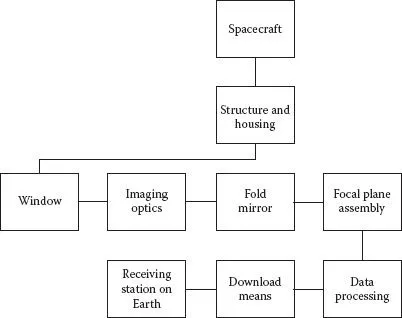
Functional block diagrams relating major portions of the system are valuable communication tools throughout the design process. Figure 1.1 shows one such diagram for a high-performance photographic system to be applied in a downward-looking, surveillance application from a spacecraft in orbit about the Earth. This system is envisioned as several major assemblies: imaging optics, a fold mirror, a focal plane assembly, a mechanical structure, and a protective housing. Ancillary subsystems accomplish data processing, storage, and downloading of images to receiving station(s) on Earth.
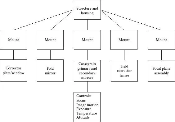
The opto-mechanical makeup of one concept for the imaging optics block of Figure 1.1 is shown in Figure 1.2. Here, we see a second-level block diagram indicating that the optical system consists conceptually of (1) an aspheric corrector plate that reduces optical aberrations and also serves as a window, (2) a folding mirror capable of redirecting the vertical input beam by 90° to the horizontal axis of the optical system, (3) image-forming optics comprising primary and secondary mirrors in the Cassegrain configuration and aberration-compensating field lenses, and (4) a focal plane assembly (envisioned as a large multipixel detector array). Each of these major components is attached to the camera structure by its own mount. An electromechanical subsystem provides means for controlling exposure and focus, for compensating image motion, and for stabilizing temperature and a computer system that coordinates required operational functions.
FIGURE 1.1
Top-level functional block diagram of a spaceborne camera.
FIGURE 1.2
Second-level block diagram for the spaceborne camera of Figure 1.1.
At the top of Figure 1.2, we see that a mechanical structure is provided to support and maintain alignment of all the camera components as well as to interface the camera with the spacecraft. A protective housing encloses the optics. This cover helps to preserve the clean and dry internal environment established during assembly.
Figure 1.3 is a preliminary schematic for the optical system. At this stage in the conceptualization process, the detailed designs of the individual components making up this system would usually not be known.
As the function of the device to be designed is examined in more detail and the subsystem technical specifications begin to take form, the relative advantages and disadvantages of this and other potential concepts can be established and weighed. Parametric trade-off analyses are often performed at this time in order to develop approximate interrelations between design variables. This helps disclose incompatibilities between specific requirements. Rough estimates of the physical size and weight of the instrument if built along alternative lines also may prove helpful in pointing out the more favorable alternative concepts. Preliminary material choices made at this time need be no more specific than to assume that optical glass would be used in lenses and windows; that...