This book deals with an area of practice that many students and non-electricians find particularly challenging. It explains how to interpret circuit diagrams and wiring systems, and outlines the principles of testing before explaining how to apply this knowledge to fault finding in electrical circuits.
A handy pocket guide for anybody who needs to be able to trace faults in circuits, whether in domestic, commercial or industrial settings, this book will be extremely useful to electricians, plumbers, heating engineers and intruder alarm installers.
Fully up to date with the 18th Edition IET Wiring Regulations 2018.
Covers all the principles and practice of testing and fault diagnosis in a way that is clear for students and non-electricians.
Expert advice from an engineering training consultant, supported with colour diagrams and key data.
▪ be aware of the correct symbols to be used on diagrams,
▪ know the different types of diagrams in general use and why they are used,
▪ understand circuit convention and its importance in interpreting diagrams,
▪ understand simple relay logic and its application to PLCs.
This is an area often overlooked or even ignored. The IET Wiring Regulations require that ‘diagrams, charts, tables or equivalent forms of information are made available’ to the installer and inspector and tester.
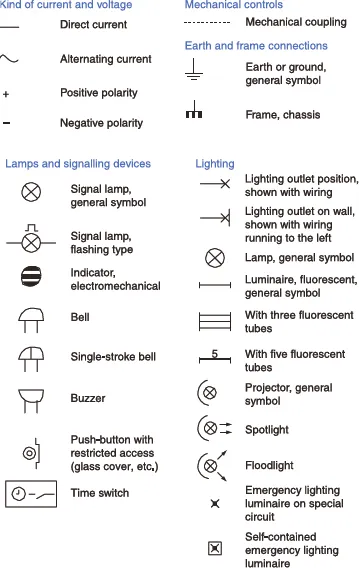
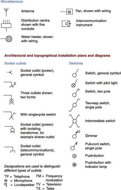
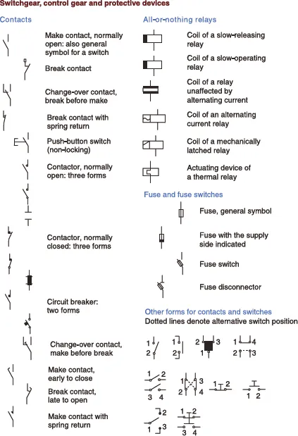
BS EN 60617 SYMBOLS
BS EN 60617 gives the graphical symbols that should be used in all electrical/electronic diagrams or drawings. Since the symbols fall in line with the International Electrotechnical Commission (IEC) document 617, it should be possible to interpret non-UK diagrams. Samples of the symbols used in this book are shown in Figure 1.1.
FIGURE 1.1 BS EN 60617 symbols.
DIAGRAMS
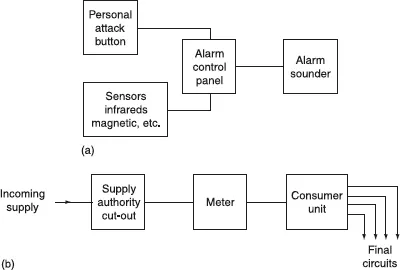
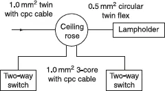
The four most commonly used diagrams are the block diagram, interconnection diagram, the circuit or schematic diagram and the wiring or connection diagram.
Block diagrams
These diagrams indicate, by means of block symbols with suitable notes, the general way in which a system functions. They do not show detailed connections (Figures 1.2a and b).
Interconnection diagrams
In this case, items of equipment may be shown in block form but with details of how the items are connected together (Figure 1.3).
Circuit or schematic diagrams
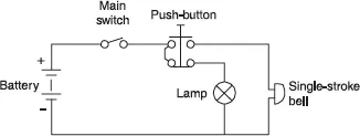
These diagrams show how a system works, and need to pay no attention to the actual geographical layout of components or parts of components in that system. For example, a pair of contacts which form part of, say, a timer may appear in a different and quite remote part of the diagram than the timer operating coil that actuates them. In this case some form of cross-reference scheme is needed (e.g. T for the timer coil and T1, T2, T3, etc. for the associated contacts).
It is usual for the sequence of events occurring in a system to be shown on a circuit diagram from left to right or from top to bottom. For example, in Figure 1.4, nothing can operate until the main switch is closed, at which time the signal lamp comes on via the closed contacts of the push-button. When the push is operated the lamp goes out and the bell is energized via the push-button’s top pair of contacts.
Wiring or connection diagrams
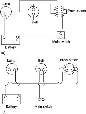
Here the diagrams show how a circuit is to be actually wired. Whenever possible, especially in the case of control panels, they should show components in their correct geographical locations.
FIGURE 1.5
The wiring between terminals may be shown individually on simple diagrams, but with complicated systems such wiring is shown in the form of thick lines with the terminating ends entering and leaving just as if the wiring were arranged in looms. Clearly, Figures 1.5a and b are the wiring diagrams associated with the circuit shown in Figure 1.4. Although Figure 1.5a would be simple to wire without reference to the circuit diagram, Figure 1.5b would present a problem as it is shown if Figure 1.4 were not available.
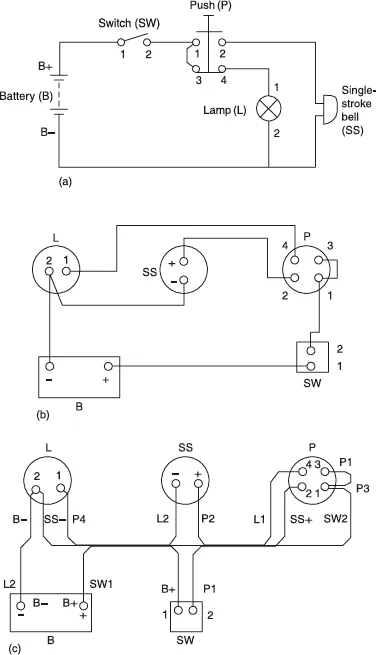
In either case an alphanumeric (A1, GY56, f7, etc.) reference system is highly desirable, not only for ease of initial wiring, but also for fault location or the addition of circuitry at a later date. Both circuit and wiring diagrams should be cross-referenced with such a system (Figures 1.6a–c).
FIGURE 1.6 Schematic and wiring diagrams.
Note how, in Figure 1.6c, each termination is referenced with the destination of the conductor connected to it. Also note how much more easily a circuit diagram makes the interpretation of the circuits function.
CIRCUIT CONVENTION
It is probably sensible at t...
Table of contents
Cover
Half Title
Title Page
Copyright Page
Preface
Chapter 1 Diagrams
Chapter 2 Wiring Systems
Chapter 3 Testing and Test Instruments
Chapter 4 Fault Finding
Appendix 1 Shock Risk and Safe Isolation
Appendix 2 Basic Electrical Theory
Appendix 3 Solutions
Index
Trusted by 375,005 students
Access to over 1.5 million titles for a fair monthly price.
Study more efficiently using our study tools.
Frequently asked questions
Yes, you can cancel anytime from the Subscription tab in your account settings on the Perlego website. Your subscription will stay active until the end of your current billing period. Learn how to cancel your subscription
No, books cannot be downloaded as external files, such as PDFs, for use outside of Perlego. However, you can download books within the Perlego app for offline reading on mobile or tablet. Learn how to download books offline
Perlego offers two plans: Essential and Complete
Essential is ideal for learners and professionals who enjoy exploring a wide range of subjects. Access the Essential Library with 800,000+ trusted titles and best-sellers across business, personal growth, and the humanities. Includes unlimited reading time and Standard Read Aloud voice.
Complete: Perfect for advanced learners and researchers needing full, unrestricted access. Unlock 1.5M+ books across hundreds of subjects, including academic and specialized titles. The Complete Plan also includes advanced features like Premium Read Aloud and Research Assistant.
Both plans are available with monthly, semester, or annual billing cycles.
We are an online textbook subscription service, where you can get access to an entire online library for less than the price of a single book per month. With over 1.5 million books across 990+ topics, we’ve got you covered! Learn about our mission
Look out for the read-aloud symbol on your next book to see if you can listen to it. The read-aloud tool reads text aloud for you, highlighting the text as it is being read. You can pause it, speed it up and slow it down. Learn more about Read Aloud
Yes! You can use the Perlego app on both iOS and Android devices to read anytime, anywhere — even offline. Perfect for commutes or when you’re on the go. Please note we cannot support devices running on iOS 13 and Android 7 or earlier. Learn more about using the app
Yes, you can access IET Wiring Regulations: Wiring Systems and Fault Finding for Installation Electricians by Brian Scaddan in PDF and/or ePUB format, as well as other popular books in Technology & Engineering & Civil Engineering. We have over 1.5 million books available in our catalogue for you to explore.