![]()
CHAPTER ONE
Planning for electromagnetic compliance
Complex systems and large installations should operate reliably without interruption or degraded performance due to electromagnetic interference. Enforced by laws around the globe, all (electronic) equipment has to fulfill certain requirements on the emission of, and the immunity to, electromagnetic disturbances. Compliance to these laws enables harmonic coexistence of equipment. In technical terms, this compliance is called electromagnetic compatibility, which is better known by its acronym EMC.
The International Electrotechnical Commission (IEC 60050-161 2017) defines EMC as
The ability of equipment or a system to function satisfactorily in its electromagnetic environment without introducing intolerable electromagnetic disturbances to anything in that environment
Obviously, the term “disturbance” is key in this IEC definition. First, the classic source–victim model will be discussed, including the source–victim matrix analysis tool for risk assessment of individual equipment. Next, the important, yet complex, concept called “environment” will be introduced. From this, the zoning concept will be derived, which in turn can be managed with a zone compatibility matrix. Both the source–victim matrix and the zone compatibility matrix are used as risk assessment tools to identify where specific EMC mitigations have to be designed. Basic EMC guidelines for systems and installations, including mitigation measures to EMC risks, are discussed in the subsequent chapters.
1.1 Source–victim model
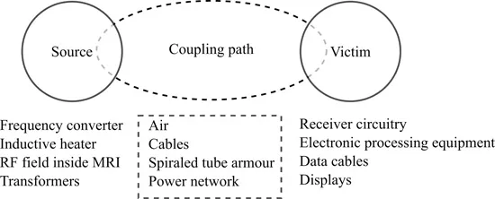
Intolerable electromagnetic interference requires both a source for creating a disturbance and a victim for which this disturbance is intolerable. In addition, a path for the disturbance to travel from the source to the victim is essential. This classic EMC model is depicted in Figure 1.1.
In this model, the source may be either natural or man-made (Degauque 1993). Examples of natural noise are thunderstorm activity, lightning strokes, and magnetic storms. Man-made noise could be arc welding, harmonics from variable frequency drives, or RF leakage from a microwave oven. Both natural noise and man-made noise are called emission by IEC: Any EM emission, natural or “man-made”, is potentially a disturbance to any other susceptible device in the environment. Susceptibility is defined as the threshold at which other equipment will start to malfunction or break down due to an external electromagnetic disturbance. Immunity is the opposite, it being the ability of equipment to function correctly in the presence of electromagnetic interference. Hardening is the discipline to reduce the susceptibility or increase the immunity of equipment. Immunity should not be mistaken for invulnerability: any electronic system will break down above a certain threshold.
FIGURE 1.1 The basic EMC model contains three essential elements: the source, the victim, and a path for the disturbance to travel from the source to the victim.
Disturbances may travel over cables (conducted) or through the air as electric (parasitic capacitance) or magnetic fields (parasitic mutual inductance) or as electromagnetic waves (radiated). This is called the coupling path. Without coupling path, the disturbance from the source will not be able to interact with the victim, and the victim will remain to function unimpaired.
1.1.1 Source–victim matrix
A source–victim matrix is created to evaluate the risk of interference between equipment parts. A sample source–victim matrix is shown in Figure 1.2. This matrix lists potential sources of disturbance as rows and the victims, for which this disturbance is intolerable, as columns.
A victim is sometimes referred to as “sink.” As will become obvious from the subsequent chapters, this term may lead to confusion. For any combination of source and victim, the risk of interference has to be assessed and entered at the crossing of the row of the source and the column of the victim in the matrix. When interference is possible, a “1” is entered; if it is likely, a “2” is entered. When interference is very unlikely, the crossing is left blank. Any equipment can be both a source for disturbance and simultaneously a victim for another disturbance, so the full matrix has to be filled.
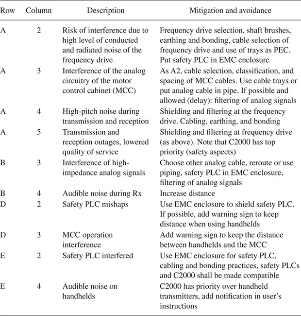
When the risk assessment shows that interference is possible, mitigation measures have to be described. When interference is likely, avoidance measures must be analyzed and described. An example is shown in Table 1.1. In this case, the frequency drive is designated as the source and the safety-PLC as the victim, and a high likelihood of interference is predicted. This is indicated with “2” at coordinate A2.
FIGURE 1.2 Example of the source–victim matrix.
Table 1.1 Overview of mitigation and avoidance measures based on the risk assessment noted in the source–victim matrix
1.2 Environments
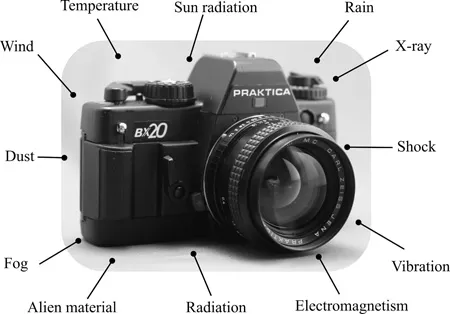
All equipment is exposed to a variety of phenomena. For example, the camera in Figure 1.3 can be shaken, sometimes dropped and used, or stored at different temperatures. These phenomena can be clustered according to their similarities in effect, for example, the first two involve shock. Such a cluster is called an environment. Every system or installation is subjected to a combination of environments. In a dynamo, a rotating magnet generates an electric voltage on purpose. In case the motion of a magnet is not intentional, the effect may be an electromagnetic disturbance. It is for this reason that the interaction between the electromagnetic environment and the installation focuses on the susceptibility of the installation.
FIGURE 1.3 The photo camera, its environments, and the environmental effects.
In complex systems and large installations, the size of the source–victim will grow to an extent that it becomes impractical to manage. Consider, for example, a (naval) vessel in which a multitude of systems have to be integrated in a limited space. It is therefore necessary to focus on the most important sources and victims.
1.2.1 Location classes
In many situations, the electromagnetic environment will be predefined by natural noise and man-made noise originating from an already installed equipment. The IEC defines three typical or archetypal location classes and related electromagnetic environments based on the prevailing electromagnetic phenomena (IEC 61000-2-5, 2017):
Residential: The residential location exists in an area of land designated for the construction of domestic dwellings, which is a place for one or more people to live.
Commercial: Commercial/public location is defined as the environment in areas of the center of a city, offices, public transport systems (road/train/underground), and modern business centers containing a concentration of office automation equipment.
Industrial: Industrial installations are characterized by the fact that many items of equipment are installed together and operated simultaneously, and some of these items of equipment might act as a severe interference source.
FIGURE 1.4 Graphical representation of location classes in EMC.
These locations are graphically depicted in Figure 1.4. When the location classes do not overlap, the environment class corresponds to the location.
1.2.2 User and intended environment
The question if a product will operate satisfactorily when immersed in a certain electromagnetic environment implicitly addresses two important aspects:
The intended environment: This is the environment which the manufacturer of the equipment has designed their product for.
The user environment: This is the environment in which the equipment will be installed and used “for real.”
The aspects show that the manufacturer can define the intended environment, while the user or system integrator often has to cope with the user environment. If, for a certain system, the intended environment and user environment coincide, the system should be sufficiently immune to interference in the user environment. On the contrary, it will not add an unacceptable interference to its environment in order to realize the interference-free operation of other equipment.
Great care must be taken to verify that the intended and user environments really coincide. The manufacturer often poses additional conditions in order to establish compliance with certain environments, for example, the type and length of cabling or the need for filtering.
Both U.S. Federal Communications Commission (FCC) and European Union directives relate the electromagnetic compliance of equipment to the intended environment. Typically, this information can be found...