eBook - ePub
Design of Masonry Structures
- 271 pages
- English
- ePUB (mobile friendly)
- Available on iOS & Android
eBook - ePub
Design of Masonry Structures
About this book
This edition has been fully revised and extended to cover blockwork and Eurocode 6 on masonry structures. This valued textbook:Discusses all aspects of design of masonry structures in plain and reinforced masonry.summarizes materials properties and structural principles as well as describing structure and content of codes.Presents design procedures
Trusted by 375,005 students
Access to over 1.5 million titles for a fair monthly price.
Study more efficiently using our study tools.
Information
1: Loadbearing masonry buildings
1.1 ADVANTAGES AND DEVELOPMENT OF LOADBEARING MASONRY
The basic advantage of masonry construction is that it is possible to use the same element to perform a variety of functions, which in a steelframed building, for example, have to be provided for separately, with consequent complication in detailed construction. Thus masonry may, simultaneously, provide structure, subdivision of space, thermal and acoustic insulation as well as fire and weather protection. As a material, it is relatively cheap but durable and produces external wall finishes of very acceptable appearance. Masonry construction is flexible in terms of building layout and can be constructed without very large capital expenditure on the part of the builder.
In the first half of the present century brick construction for multistorey buildings was very largely displaced by steel- and reinforcedconcrete-framed structures, although these were very often clad in brick. One of the main reasons for this was that until around 1950 loadbearing walls were proportioned by purely empirical rules, which led to excessively thick walls that were wasteful of space and material and took a great deal of time to build. The situation changed in a number of countries after 1950 with the introduction of structural codes of practice which made it possible to calculate the necessary wall thickness and masonry strengths on a more rational basis. These codes of practice were based on research programmes and building experience, and, although initially limited in scope, provided a sufficient basis for the design of buildings of up to thirty storeys. A considerable amount of research and practical experience over the past 20 years has led to the improvement and refinement of the various structural codes. As a result, the structural design of masonry buildings is approaching a level similar to that applying to steel and concrete.
1.2 BASIC DESIGN CONSIDERATIONS
Loadbearing construction is most appropriately used for buildings in which the floor area is subdivided into a relatively large number of rooms of small to medium size and in which the floor plan is repeated on each storey throughout the height of the building. These considerations give ample opportunity for disposing loadbearing walls, which are continuous from foundation to roof level and, because of the moderate floor spans, are not called upon to carry unduly heavy concentrations of vertical load. The types of buildings which are compatible with these requirements include flats, hostels, hotels and other residential buildings.
The form and wall layout for a particular building will evolve from functional requirements and site conditions and will call for collaboration between engineer and architect. The arrangement chosen will not usually be critical from the structural point of view provided that a reasonable balance is allowed between walls oriented in the principal directions of the building so as to permit the development of adequate resistance to lateral forces in both of these directions. Very unsymmetrical arrangements should be avoided as these will give rise to torsional effects under lateral loading which will be difficult to calculate and which may produce undesirable stress distributions.
Stair wells, lift shafts and service ducts play an important part in deciding layout and are often of primary importance in providing lateral rigidity.
The great variety of possible wall arrangements in a masonry building makes it rather difficult to define distinct types of structure, but a rough classification might be made as follows:
- Cellular wall systems
- Simple or double cross-wall systems
- Complex arrangements.
A cellular arrangement is one in which both internal and external walls are loadbearing and in which these walls form a cellular pattern in plan. Figure 1.1 (a) shows an example of such a wall layout.
The second category includes simple cross-wall structures in which the main bearing walls are at right angles to the longitudinal axis of the building. The floor slabs span between the main cross-walls, and longitudinal stability is achieved by means of corridor walls, as shown in Fig. 1.1(b). This type of structure is suitable for a hostel or hotel building having a large number of identical rooms. The outer walls may be clad in non-loadbearing masonry or with other materials.
It will be observed that there is a limit to the depth of building which can be constructed on the cross-wall principle if the rooms are to have effective day-lighting. If a deeper block with a service core is required, a somewhat more complex system of cross-walls set parallel to both major axes of the building may be used, as in Fig. 1.1(c).
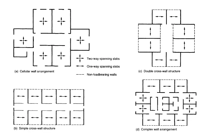
Fig. 1.1 Typical wall arrangements in masonry buildings.
All kinds of hybrids between cellular and cross-wall arrangements are possible, and these are included under the heading ‘complex’, a typical example being shown in Fig. 1.1(d).
Considerable attention has been devoted in recent years to the necessity for ensuring the ‘robustness’ of buildings. This has arisen from a number of building failures in which, although the individual members have been adequate in terms of resisting their normal service loads, the building as a whole has still suffered severe damage from abnormal loading, resulting for example from a gas explosion or from vehicle impact. It is impossible to quantify loads of this kind, and what is required is to construct buildings in such a way that an incident of this category does not result in catastrophic collapse, out of proportion to the initial forces. Meeting this requirement begins with the selection of wall layout since some arrangements are inherently more resistant to abnormal forces than others. This point is illustrated in Fig. 1.2: a building consisting only of floor slabs and cross-walls (Fig. 1.2(a)) is obviously unstable and liable to collapse under the influence of small lateral forces acting parallel to its longer axis. This particular weakness could be removed by incorporating a lift shaft or stair well to provide resistance in the weak direction, as in Fig. 1.2(b). However, the flank or gable walls are still vulnerable, for example to vehicle impact, and limited damage to this wall on the lowermost storey would result in the collapse of a large section of the building.
A building having a wall layout as in Fig. 1.2(c) on the other hand is clearly much more resistant to all kinds of disturbing forces, having a high degree of lateral stability, and is unlikely to suffer extensive damage from failure of any particular wall.
Robustness is not, however, purely a matter of wall layout. Thus a floor system consisting of unconnected precast planks will be much less resistant to damage than one which has cast-in-situ concrete floors with two-way reinforcement. Similarly, the detailing of elements and their connections is of great importance. For example, adequate bearing of beams and slabs on walls is essential in a gravity structure to prevent possible failure not only from local over-stressing but also from relative movement between walls and other elements. Such movement could result from foundation settlement, thermal or moisture movements. An extreme case occurs in seismic areas where positive tying together of walls and floors is essential.
The above discussion relates to multi-storey, loadbearing masonry buildings, but similar considerations apply to low-rise buildings where there is the same requirement for essentially robust construction.
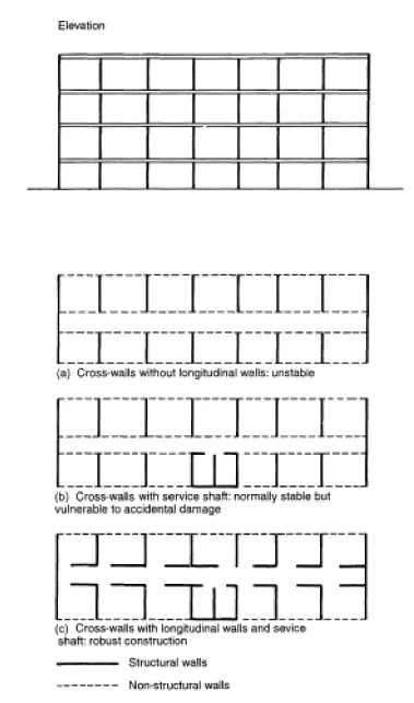
Fig. 1.2 Liability of a simple cross-wall structure to accidental damage.
1.3 STRUCTURAL SAFETY: LIMIT STATE DESIGN
The objective of ensuring a fundamentally stable or robust building, as discussed in section 1.2, is an aspect of structural safety. The measures adopted in pursuit of this objective are to a large extent qualitative and conceptual whereas the method of ensuring satisfactory structural performance in resisting service loads is dealt with in a more quantitative manner, essentially by trying to relate estimates of these loads with estimates of material strength and rigidity.
The basic aim of structural design is to ensure that a structure should fulfil its intended function throughout its lifetime without excessive deflection, cracking or collapse. The engineer is expected to meet this aim with due regard to economy and durability. It is recognized, however, that it is not possible to design structures which will meet these requirements in all conceivable circumstances, at least within the limits of financial feasibility. For example, it is not expected that normally designed structures will be capable of resisting conceivable but improbable accidents which would result in catastrophic damage, such as impact of a large aircraft. It is, on the other hand, accepted that there is uncertainty in the estimation of service loads on structures, that the strength of construction materials is variable, and that the means of relating loads to strength are at best approximations. It is possible that an unfavourable combination of these circumstances could result in structural failure; design procedures should, therefore, ensure that the probability of such a failure is acceptably small.
The question then arises as to what probability of failure is ‘acceptably small’. Investigation of accident statistics suggests that, in the context of buildings, a one-in-a-million chance of failure leading to a fatality will be, if not explicitly acceptable to the public, at least such as to give rise to little concern. In recent years, therefore, structural design has aimed, indirectly, to provide levels of safety consistent with a probability of failure of this order.
Consideration of levels of safety in structural design is a recent development and has been applied through the concept of ‘limit state’ design. The definition of a limit state is that a structure becomes unfit for its intended purpose when it reaches that particular condition. A limit state may be one of complete failure (ultimate limit state) or it may define a condition of excessive deflection or cracking (serviceability limit state). The advantage of this approach is that it permits the definition of direct criteria for strength and serviceability taking into account the uncertainties of loading, strength and structural analysis as well as questions such as the consequences of failure.
The essential principles of limit state design may be summarized as follows. Considering the ultimate limit state of a particular structure, for failure to occur:
R* — S* ≤ 0(1.1)
where R * = Rk/ γm is the design strength of the structure, and S* = f (γf Qk) the design loading effects. Here γm and γf are partial safety factors; Rk and Qk are characteristic values of resistance and load actions, generally chosen such that 95% of samples representing Rk will exceed this value and 95% of the applied forces will be less than Qk.
The probability of failure is then:
P [R* — S* ≤ 0] = p(1.2)
If a value of p, say 106, is prescribed it is possible to calculate values of the partial safety factors, γm and γf, in the limit state equation which would be consistent with this probability of failure. In order to do this, however, it is necessary to define the load effects and structural resistance in statistical terms, which in practice is rarely possible. The partial safety factors, therefore, cannot be calculated in a precise way and have to be determined on the basis of construction experience and laboratory testing against a background of statistical theory. The application of the limit state approach as exemplified by the British Code of Practice BS 5628 and Eurocode 6 (EC 6) is discussed in Chapter 4.
1.4 FOUNDATIONS
Building structures in loadbearing masonry are characteristically stiff in the vertical direction and have a limited tolerance for differential movement of foundations. Studies of existing buildings have suggested that the maximum relative deflection (i.e. the ratio of deflection to the length of the deflected part) in the walls of multi-storeyed loadbearing brickwork buildings should not exceed 0.0003 in sand or hard clay and 0.0004 in soft clay. These figures apply to walls whose length exceeds three times their height. It has also been suggested that the maximum average settlement of a brickwork building should not exceed 150 mm. These figures are, however, purely indicative, and a great deal depends on the rate of settlement as well as on the characteristics of the masonry. Settlement calculations by normal soil mechanics techniques will indicate whether these limits are likely to be exceeded. Where problems have arisen, the cause has usually been associated with particular types of clay soils which are subject to excessive shrinkage in periods of dry weather. In these soils the foundations should be at a depth of not less than 1 m in order to avoid moisture fluctuations.
High-rise masonry buildings are usually built on a reinforced concrete raft of about 600mm thickness. The wall system stiffens the raft and helps to ensure uniform ground pressures, whilst the limitation on floor spans which applies to such structures has the effect of minimizing the amount of reinforcement required in the foundation slab. Under exceptionally good soil conditions it may be possible to use spread footings, whilst very unfavourable conditions may necessitate piling with ground beams.
1.5 REINFORCED AND PRESTRESSED MASONRY
The preceding paragraphs in this chapter have been concerned with the use of unreinforced masonry. As masonry has relatively low strength in tension, this imposes certain restrictions on its field of application. Concrete is, of course, also a brittle material but this limitation is overcome by the introduction of reinforcing steel or by prestressing. The corresponding use of these techniques in masonry construction is not new but, until recently, has not been widely adopted. This was partly due to the absence of a satisfactory code of practice, but such codes are now available so that more extensive use of reinforced and prestressed masonry may be expected in future.
By the adoption of reinforced or prestressed construction the scope of masonry can be considerably extended. An example is the use of prestressed masonry walls of cellular or fin construction for sports halls and similar buildings where the requirement is for walls some 10 m in height supporting a long span roof. Other exampl...
Table of contents
- Cover Page
- Title Page
- Copyright Page
- Preface to the third edition
- Preface to the second edition
- Preface to the first edition
- Acknowledgements
- 1 Loadbearing masonry buildings
- 2 Bricks, blocks and mortars
- 3 Masonry properties
- 4 Codes of practice for structural masonry
- 5 Design for compressive loading
- 6 Design for wind loading
- 7 Lateral load analysis of masonry panels
- 8 Composite action between walls and other elements
- 9 Design for accidental damage
- 10 Reinforced masonry
- 11 Prestressed masonry
- 12 Design calculations for a seven-storey dormitory building according to BS 5628
- 13 Movements in masonry buildings
- Notation
- Definition of terms used in masonry
- References and further reading
Frequently asked questions
Yes, you can cancel anytime from the Subscription tab in your account settings on the Perlego website. Your subscription will stay active until the end of your current billing period. Learn how to cancel your subscription
No, books cannot be downloaded as external files, such as PDFs, for use outside of Perlego. However, you can download books within the Perlego app for offline reading on mobile or tablet. Learn how to download books offline
Perlego offers two plans: Essential and Complete
- Essential is ideal for learners and professionals who enjoy exploring a wide range of subjects. Access the Essential Library with 800,000+ trusted titles and best-sellers across business, personal growth, and the humanities. Includes unlimited reading time and Standard Read Aloud voice.
- Complete: Perfect for advanced learners and researchers needing full, unrestricted access. Unlock 1.5M+ books across hundreds of subjects, including academic and specialized titles. The Complete Plan also includes advanced features like Premium Read Aloud and Research Assistant.
We are an online textbook subscription service, where you can get access to an entire online library for less than the price of a single book per month. With over 1.5 million books across 990+ topics, we’ve got you covered! Learn about our mission
Look out for the read-aloud symbol on your next book to see if you can listen to it. The read-aloud tool reads text aloud for you, highlighting the text as it is being read. You can pause it, speed it up and slow it down. Learn more about Read Aloud
Yes! You can use the Perlego app on both iOS and Android devices to read anytime, anywhere — even offline. Perfect for commutes or when you’re on the go.
Please note we cannot support devices running on iOS 13 and Android 7 or earlier. Learn more about using the app
Please note we cannot support devices running on iOS 13 and Android 7 or earlier. Learn more about using the app
Yes, you can access Design of Masonry Structures by A.W. Hendry, B.P. Sinha, S.R. Davies, A.W. Hendry,B.P. Sinha,S.R. Davies in PDF and/or ePUB format, as well as other popular books in Technology & Engineering & Architecture Methods & Materials. We have over 1.5 million books available in our catalogue for you to explore.