![]()
Section Four
Grading of built elements
The following section builds on the concepts learned in the previous sections, moving from man-made landscape elements to built structures. Regardless of the type of materials used to build these structures the principles of grading are the same. All of these elements have impermeable or semipermeable surfaces which require efficient grading to promptly divert surface water runoff.
4.1 Roads, shoulders, curbs, and sidewalks
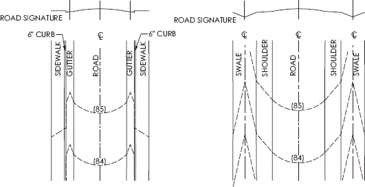
In their simplest form, most roads are ridges, shoulders and sidewalks are plane surfaces, and curbs are mini walls. Roads are built as ridges in order to ensure fast surface drainage and to prevent ponding. Roads vary depending on whether they are located in rural or urban areas, see Figure 4.1–1. Many rural roads have a shoulder and a swale and all urban roads have a gutter and connect to a closed drainage system. Some urban roads have shoulders and curbs, suburban roads are a combination of both types.
4.1–1
Urban road and rural road
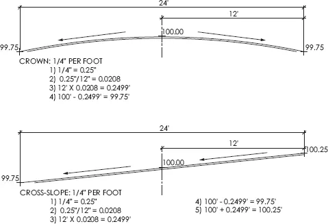
4.1–2
Crowned road and road with a uniform cross slope
Roads have three distinct parts: a longitudinal slope called a gradient, which determines whether a road is ascending or descending in relation to the surrounding topography; the centerline which is often a ridgeline called the crown of the road, and the cross slope which makes the road slope away from the crown on both sides or creates a uniform cross slope across the road.
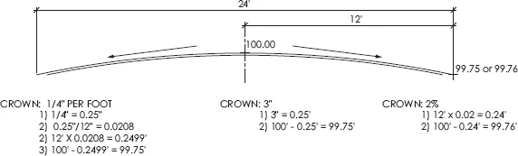
Roads will have a crown, a reverse crown or a cross slope. From a crown, the width of the road will usually slope evenly on both sides. In Figure 4.1–2, for example, if a 24′ wide road has a crown of 1/4″ per foot then the road slopes evenly on both sides from the centerline at 1/4″ per foot. A reverse crown is a swale with contours that point uphill. Although these are not as common in practice, they are sometimes shown on the LARE so make sure to confirm what is required by the problem. Most road problems have crowned roads that are ridges. Not all roads have crowns, some are sloped to one side. Roads that are pitched to one side have a cross slope. Grading a road with a cross slope is similar to grading a uniformly-sloped plane surface. The crown of a road may be called out in a variety of ways; as inches per foot, as a percentage, or in inches. Figure 4.1–3 illustrates the different calculations for the crown of a road.
It is often the case when you see a road in plan view that the contours lines are spaced evenly; this suggests a road that is rising or falling at a consistent gradient. If you see the contour lines of the road grow closer together or farther apart then you are looking at the effects of two different gradients combining to create a vertical curve. If you see the ridges of the road elongating on one side and contracting on the other then you are looking at the effects of a horizontal curve. Section 6 has additional information about horizontal and vertical curves.
4.1–3
Calculations for the slope of a crowned road
The one thing that is consistent with all roads is their uniformity. They remove the randomness of natural ridge topography and apply a very definite recognizable shape. It takes multiple steps to determine the contour lines for a road, but because of the road’s uniformity the calculations only have to be done once and then the resultant contour line is copied for each subsequent contour line of the road.
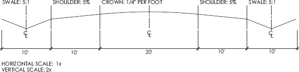
Some grading problems will provide a road cross-section as illustrated in Figure 4.1–4. The cross section outlines the cross slopes of the different elements of the road and some will provide written text of the different longitudinal and cross slopes for the road, others still will provide only spot elevations from which you must determine the appropriate slopes.
Regardless of the way it is presented, the solution is essentially the same. Solve for each of the necessary parameters, draw one contour line, and use the slope interval for the road gradient to complete the subsequent contour lines along the road. The road gradient is often provided; however, sometimes two or more spot elevations are provided along the road and the longitudinal slope has to be calculated. The following example shows the steps for creating proposed contours for a road with a 4% gradient and its supporting structures, swales, curbs, gutters and sidewalks.
4.1–4
Typical road cross section showing crown, shoulder, and swale
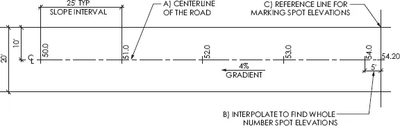
1 Create a centerline down the middle of the road and using the slope formula and interpolation mark off whole number spot elevations.
2 Label these whole number spot elevations on the uphill side of the line so that the downhill direction is readily apparent, see Figure 4.1–5.
3 Draw a very light perpendicular line through the starting spot elevation across the width of the road include any curb, shoulder, swale or gutter areas on the grading problem. This guideline is used for the cross slopes of the different elements and will make copying the answer for each contour line easier. The road gradient will apply to all elements of the road.
4 Next, determine how much the topography will descend or ascend on the reference line from the crown of the road. Interpolate using the crown or cross slope for the road to determine the spot elevation at the edge of the road on both sides, see Figure 4.1–6.
4.1–5
Road with centerline, light reference line, and whole number spot elevations
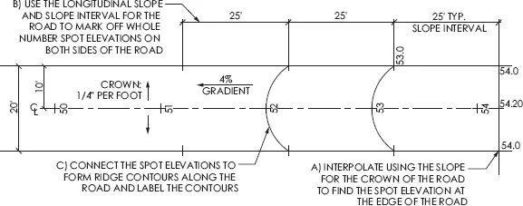
4.1–6
Road with spot elevations marked off along reference line
5 Mark the spot elevation at the edge of the road where it intersects with the reference line.
6 Determine where the whole number spot elevations occur along the edge of the road using the slope interval of the road gradient.
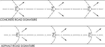
7 Mark off the whole number spot elevations for all whole number spot elevations on both sides of the road. Before completing the road contour line, determine if the road is asphalt or concrete. A concrete road will create a chevron topographically and an asphalt road will create a parabola, see Figure 4.1–7. Remember that a ridge points downhill. Use arrows to help visualize the direction of water flow and the correct curve for the crown of the road.
8 Connect the whole number spot elevations from the crown of the road to the edges of the road, creating contour lines for the road; use smooth, continuous lines.
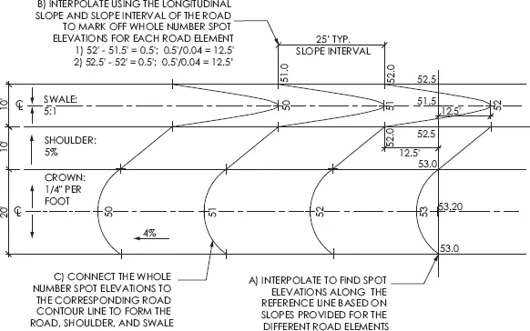
9 The procedure is the same for the other elements along the road, the shoulder, the gutter and the swale. Using the reference line, calculate the vertical change for the shoulder or swale based on their cross slopes and add the spot elevation to the reference line, see Figure 4.1–8.
10 Use interpolation to find the nearest whole number spot elevations uphill or downhill from the reference line. Use the road gradient slope interval to quickly mark off the other whole number spot elevations along the shoulder or swale.
11 Connect the whole number spot elevations to the road contour line. Repeat for each contour line.
If a deep swale is required, make sure to mark off the whole number spot elevations along the reference line as well as along the centerline for the swale. In Figure 4.1–9 for example, if a slope of 3:1 is provided for a 2′ deep swale at the edge of the road, make sure that between the spot elevations on the reference line you interpolate to determine the whole number contours. These will be used to help draw the swale. If a swale is not present a gutter may be provided to direct water into a closed drainage system; the calculation is the same as for a swale.
4.1–7
Concrete and asphalt road signatures
4.1...