- 347 pages
- English
- ePUB (mobile friendly)
- Available on iOS & Android
eBook - ePub
About this book
Crossbar switch fabrics offer many benefits when designing switch/routers. This book discusses switch/router architectures using design examples and case studies of well-known systems that employ crossbar switch fabric as their internal interconnects. This book looks to explain the design of switch/routers from a practicing engineer's perspective. It uses a broad range of design examples to illustrate switch/router designs and provides case studies to enhance readers comprehension of switch/router architectures. The book goes on to discuss industry best practices in switch/router design and explains the key features and differences between unicast and multicast packet forwarding architectures. This book will be of benefit to telecoms/networking industry professionals and engineers as well as researchers and academics looking for more practical and efficient approaches for designing non-blocking crossbar switch fabrics.
Trusted by 375,005 students
Access to over 1.5 million titles for a fair monthly price.
Study more efficiently using our study tools.
Information
Part 1
Characteristics of Switch/Routers with Crossbar Switch Fabrics
1 The Switch/Router
Integrated OSI Layers 2 and 3 Forwarding on a Single Platform
1.1 INTRODUCTION
This chapter introduces switch/routers and the architectures and methods they support to perform multilayer switching. An understanding of multilayer switching is necessary for the reader to better appreciate the various architectures discussed in this book. A switch/router, sometimes referred to as a multilayer switch, is a device that supports the forwarding of packets at both Layers 2 and 3 of the Open Systems Interconnection (OSI) model (Figure 1.1).
The switch/router also supports the relevant Layers 2 and 3 control plane protocols needed to create the forwarding databases used in the forwarding of packets [AWEYA1BK18]. In addition to features for system management and configuration, the switch/router may support quality-of-service (QoS) and security filtering and control mechanisms that use parameters within the Layers 4 to 7 fields of packets being forwarded.
Network devices attached to different virtual local area networks (VLANs) can only communicate with one another through a router (or Layer 3 forwarding device) as illustrated in Figure 1.1. In a Layer 2 network, VLANs can be used to define distinct and separate broadcast domains. Each defined broadcast domain (or VLAN) is the set of devices attached to that domain that can receive Layer 2 broadcast packets (e.g., Ethernet frames) sent from any device within that domain.
Routers are typically used to bound the distinct broadcast domains (VLANs) because routers do not forward broadcast frames—all broadcast traffic within a VLAN is confined to that VLAN and cannot cross any attached router. VLANs are designed to mimic the behavior of legacy shared-medium LAN segments where broadcasts from any one device are seen by all other devices on that LAN segment.
Layer 2 forwarding is relatively simple compared to Layer 3 forwarding [AWEYA1BK18]. To perform Layer 3 forwarding, the switch/router needs a route processor (also referred to as Layer 3 control engine) that runs the routing and management protocols for the system. The routing protocols build and maintain the routing tables required for Layer 3 forwarding. In addition to creating the routing and forwarding databases (tables), the route processor also performs all the non-data transfer housekeeping functions for the system (system configuration, monitoring, download of software to other modules, management of QoS and security access control lists (ACL), and other tasks for packet processing).

FIGURE 1.1 Layers 2 and 3 Forwarding in the Switch/Router.
A switch/router can use either flow-based or network topology-based information for Layer 3 packet forwarding. The advantages and disadvantages of both methods have been discussed in greater detail in [AWEYA1BK18]. Nonetheless, we give a brief overview of these methods later to set the proper context for the discussions that follow in the later chapters.
1.2 FLOW-BASED LAYER 3 FORWARDING
In flow-based Layer 3 forwarding, the switch/router maintains a flow/route cache of the forwarding information of recently processed packets (e.g., destination IP address, next-hop IP node (and its receiving interface MAC address), egress port, and any other relevant forwarding information). To populate the flow/route cache, the switch/router forwards the first packet in any flow to the route processor for software-based processing and forwarding using the route processor’s master forwarding table.
After the first packet of the flow is forwarded, the forwarding information used by the route processor is used to populate the flow/route cache so that subsequent packets of the same flow can be forwarded using the simpler and faster flow/route cache. The basic concepts of flow-based Layer 3 forwarding are illustrated in Figure 1.2.

FIGURE 1.2 Layer 3 Forwarding Using Flow-Based Forwarding Table (or Flow/Route Cache).
To enable high-speed Layer 3 packet forwarding, the switch/router typically employs specialized application-specific integrated circuits (ASIC) to perform the forwarding and all the relevant Layers 2 and 3 packet rewrite operations of the forwarded packets. The main Layer 3 (or IP) packet rewrites include updating the time-to-live (TTL) value and recalculating the IP checksum. The basic Layer 2 rewrites (assuming Ethernet is used) include rewriting the source MAC address in the outgoing packet to be that of the egress interface, rewriting the destination MAC address to be that of the receiving interface of the next-hop node, and recalculating the Ethernet checksum.
The Ethernet checksum recalculation is necessary because the source and destination MAC addresses of the packet change as the packet traverses the switch/router when forwarded at Layer 3. The switch/router is required to recalculate the Ethernet checksum as these new MAC addresses are written in the outgoing packet. The packet forwarding may include more rewrites such as adding VLAN tags, updating IP and/or Ethernet packet class-of-service information, and so on.
1.3 NETWORK TOPOLOGY-BASED LAYER 3 FORWARDING
In topology-based forwarding, the route processor runs the routing protocols to create the routing tables. Entries in the routing table can also be created manually as static routes. The most relevant information needed for packet forwarding is distilled from the routing table to generate the more compact forwarding table. The forwarding table contains the same information needed to forward packets as the routing table, the only difference is it contains only the information that can be used directly by a forwarding engine in forwarding packets—it excludes all other information not needed for forwarding.
In topology-based forwarding, the forwarding engine performs Layer 3 forwarding using the Layer 3 forwarding table (also called the forwarding information base (FIB)) and Layer 2 rewrites using information maintained in the adjacency table which is dynamically updated by Layer 2 address discovery protocols such as the Address Resolution Protocol (ARP). Using the Layer 3 forwarding and Layer 2 adjacency tables, the forwarding engine can quickly perform lookups for forwarding information such as a packet’s next-hop IP address, egress port, and MAC address of the receiving interface of the next-hop IP node (Figure 1.3).
For topology-based forwarding, the following two main databases are used by the forwarding engine:
- Layer 3 Forwarding Table: The forwarding engine performs lookups in a Layer 3 forwarding table for the forwarding information of a packet. Each lookup is performed by extracting the IP destination address of the packet and then making a longest prefix matching (LPM) search in the forwarding table. LPM is more complex than lookups in a flow/route cache and can be time consuming and processing intensive when performed in software. High-speed, high-performance LPM searches are generally done in hardware. Conceptually, the Layer 3 forwarding table is similar to the routing table albeit rather compact and smaller. The forwarding table contains the same forwarding information maintained in the routing table. The routing table is updated (dynamically by the routing protocols) whenever topology or routing changes occur in the network. The forwarding table is then immediately updated to reflect these changes. The routing table and forwarding table must always be kept synchronized as much as possible. The forwarding table maintains information such as the next-hop IP address information and the corresponding egress port on the switch/router.
 FIGURE 1.3 Layer 3 Forwarding Using Network Topology-Based Forwarding Table.
 - Adjacency Table: Two nodes in a network are considered adjacent if they can reach each other over a single Layer 2 protocol hop (e.g., Ethernet, Point-to-Point Protocol (PPP), Asynchronous Transfer Mode (ATM), IEEE 802.11, etc.). The adjacency table is used to maintain Layer 3 address to Layer 2 address mapping. The adjacency table maintains a Layer 2 (e.g., MAC) address for every next-hop IP address in the forwarding table. Before a packet is transmitted out its egress port, the Layer 2 destination address in the outgoing packet is rewritten using the Layer 2 address information read from the adjacency table. This Layer 2 address is that of the receiving interface of the next-hop IP node (the Layer 2 adjacency of the current node). The adjacency table can be integrated into the Layer 3 forwarding table or implemented as a separate table. However, integrating it into the forwarding table allows one lookup to be performed to retrieve all forwarding information including the Layer 2 adjacencies.
The topology-based forwarding model allows the separation (or decoupling) of the control-plane functions (i.e., running routing and control protocols) from the data-plane functions (i.e., forwarding table lookups and packet rewrites). Nevertheless, the control-plane functions (running software in the route processor) are still responsible for creating and maintaining the master forwarding and adjacency tables and then downloading these to the data-plane functions (running in the forwarding engine(s)).
A switch/router may support multiple route processors for redundancy purposes (e.g., primary and secondary route processors running in active-active or active-standby mode). A switch/router may also support multiple forwarding engines running in a distributed manner each using a copy of the master forwarding table maintained by the route processor.
The forwarding engine may not be able to forward all packets it receives. These special packets have to be forwarded to the route processor for further processing. Examples of these special (or exemption) packets are:
- Control packets from routing protocols
- IP packets with IP header options
- IP packets requiring fragmentation
- Packets with IP time-to-live (TTL) expired
- Packets carrying ICMP echo requests (used to ping IP devices)
- IP packets coming from or destined to tunnel interfaces
- Packets requiring encryption, network address translation, etc.
1.4 USING CENTRALIZED OR DISTRIBUTED FORWARDING ENGINES
Packet forwarding can be done using one of two methods, centralized or distributed.
1.4.1 Forwarding Using a Centralized Forwarding Engine
In centralized forwarding, a single centralized forwarding engine or a pool of them perform all packet forwarding decisions for all packets received from all network interfaces in the system. In addition to making forwarding decisions, the centralized forwarding engine(s) perform the QoS and security ACL processing and filtering as well as other data-path functions required in the system.
All packets entering the switch/router must pass through the centralized forwarding engine to be processed. Incoming packets are passed from the network interfaces over the switch fabric (which can be a shared-bus, shared-memory or crossbar switch) to the central forwarding engine. Figure 1.4 illustrates the logical architectures of centralized forwarding.
Some centralized forwarding architectures offload some amount of the data-path processing to the line cards or interface modules by allowing them to forward only the packet headers to the centralized forwarding engine [BRYAN93] [CISCCAT6000]. The storage of the packet payloads and some packet rewrite operations are carried out in the line cards. Examples of these kinds of architecture are described in detail in [AWEYA1BK18] and also in Chapters 4 and 8 of this book.
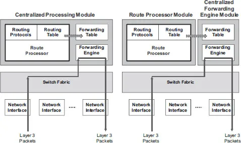
FIGURE 1.4 Centralized Forwarding.
1.4.2 Forwarding Using Distributed Forwarding Engines
In a distributed forwarding architecture, multiple independent forwarding engines are spread out in the system, located typically in the line cards (or network interface modules). This allows the interfaces or line cards to make forwarding decisions independently using their local copies of the forwarding tables downloaded from the route processor (Figure 1.5). In this architecture, the centralized route processor generates the master forwarding table but also ensures that the distributed forwarding tables are kept synchronized to the master table.
The route processor runs the routing protocols to create both the routing table and the master Layer 3 forwarding table. The route processor then copies the contents of its master tables to local forwarding tables used by the distributed forwarding engines located on the line cards. This allows each line card to make forwarding decisions independently without direct assistance from the centralized route processor. An incoming packet is processed by its ingress line card and then transferred directly across the switch fabric to its destination egress line card.
Each line card in the distributed architecture uses its copy of the master forwarding table and adjacency table for forwarding packets. Some architectures with local ARP processing capabilities on the line cards may allow the line card to main a local ARP (or adjacency) table which is created and maintained by the local ARP module. Other architectures may relegate all ARP processing to the centralized route processor, which creates all adjacencies for the entire system. Designers who aim to keep the cost and complexity of the line card low (by not including more processing beyond pure data-path processing) adopt this centralized ARP processing approach.

FIGURE 1.5 Distributed Forwarding.
High-capacity, high-performance routing systems are generally based on distributed forwarding architectures. The forwarding performance and throughput with distributed forwarding is equal to the aggregate throughput of all the distributed forwarding engines as long as the switch fabric is not a bottleneck. The distributed forwarding architecture also allows each line card to be specifically designed to support its own unique set of local functions and interfaces (encryption, network address translation capabilities, tunneling protocols, different types of Layer 2 protocols and encapsulations, mix of interface types and s...
Table of contents
- Cover
- Half Title
- Title
- Copyright
- Contents
- Preface
- Author
- Part 1 Characteristics of Switch/Routers with Crossbar Switch Fabrics
- Part 2 Design Examples and Case Studies
- Index
Frequently asked questions
Yes, you can cancel anytime from the Subscription tab in your account settings on the Perlego website. Your subscription will stay active until the end of your current billing period. Learn how to cancel your subscription
No, books cannot be downloaded as external files, such as PDFs, for use outside of Perlego. However, you can download books within the Perlego app for offline reading on mobile or tablet. Learn how to download books offline
Perlego offers two plans: Essential and Complete
- Essential is ideal for learners and professionals who enjoy exploring a wide range of subjects. Access the Essential Library with 800,000+ trusted titles and best-sellers across business, personal growth, and the humanities. Includes unlimited reading time and Standard Read Aloud voice.
- Complete: Perfect for advanced learners and researchers needing full, unrestricted access. Unlock 1.5M+ books across hundreds of subjects, including academic and specialized titles. The Complete Plan also includes advanced features like Premium Read Aloud and Research Assistant.
We are an online textbook subscription service, where you can get access to an entire online library for less than the price of a single book per month. With over 1.5 million books across 990+ topics, we’ve got you covered! Learn about our mission
Look out for the read-aloud symbol on your next book to see if you can listen to it. The read-aloud tool reads text aloud for you, highlighting the text as it is being read. You can pause it, speed it up and slow it down. Learn more about Read Aloud
Yes! You can use the Perlego app on both iOS and Android devices to read anytime, anywhere — even offline. Perfect for commutes or when you’re on the go.
Please note we cannot support devices running on iOS 13 and Android 7 or earlier. Learn more about using the app
Please note we cannot support devices running on iOS 13 and Android 7 or earlier. Learn more about using the app
Yes, you can access Switch/Router Architectures by James Aweya in PDF and/or ePUB format, as well as other popular books in Technology & Engineering & Computer Networking. We have over 1.5 million books available in our catalogue for you to explore.