![]() Fundamentals
Fundamentals![]()
Chapter 1
BIM overview
THIS CHAPTER PROVIDES a broad overview of building information modeling, explains the virtual building model metaphor, and categorizes the building information model into “dimensions” that illustrate the potential for its usefulness across the lifetime of a building project. The acronym BIM will be used to refer to the three-dimensional (3D) data-rich digital model (“the BIM”), the act of modeling, and the process of integrated design and delivery using BIM.
Parametric modeling and the virtual building model
HOW IS BIM SUBSTANTIALLY different from computer-aided design (CAD) and other types of 3D modeling programs? BIM is not CAD – CAD traditionally refers to a computer-aided design or computer-aided drafting program that has been optimized for producing two-dimensional (2D) drawings of objects such as buildings, airplanes, mechanical parts, electrical layouts, etc. BIM is not just 3D CAD; it is instead an integrated database of construction information, including building components. The conjunction of 3D graphics, parametric modeling, and user-supplied data creates the virtual design and construction model. At its best, BIM is an integrated, structured digital database, informed by the architecture, engineering, construction, operations (AECO) industry that consists of 3D parametric objects and allows for interoperability.
BIM’s fundamental characteristic is that it is a collection of parametric objects that contain data. This is not only dissimilar from CAD, but also other types of 3D modeling programs. CAD programs are also composed of objects – lines, circles, text, splines, rectangles, ellipses, and others, that are defined by formulas. Inherently independent of screen or output resolution, CAD is vector-based software, which maintains excellent graphic quality. Editing is done at the object level, and limited types of geometric information can be derived from these objects, for example, length, floor area, and perimeter. These basic elements can be grouped together into symbols depicting architectural elements as simple as doors and windows but also more complex objects. Using these components and adding attributes, typically non-graphical data associated with the library object, produces a primitive BIM composed of 2D objects with information that can be assembled into a building. Quantities can be ascertained, and bills of materials and cost estimates generated. Add transformations, editing of objects and graphic primitives, special characteristics of double-lined “walls,” the concept of layers for viewing, and early 3D features, and one has an adequate description of commercially available CAD systems of the late 1980s. Information content has increased from being merely simple drawing objects to full-featured architectural components. However, this is still not a building information model.
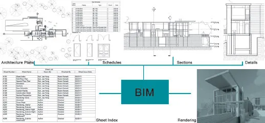
1.1 The BIM is a single database that can be used for a variety of purposes (thanks to Arlyn Ramirez-Diaz and Jae Yong Suk).
The viewing mechanism in most CAD systems depends on the visibility of layers, which can be conceived of as virtual sheets of paper with discipline or trade specific information (architecture, structural grid, electrical layout, furniture, etc.). Another less common method of organizing CAD elements relied on named objects (A:DOOR:INTERIOR:WOOD, A:WALLS:INTERIOR:KITCHEN, S:GRID:COLUMN:F-12) or assemblies. This system was more popular outside the USA in countries that use the CI-Sfb system (analogous to the Construction Specification Institute’s MasterSpec Uniformat).
The layering system approach became very popular with the use of CAD programs; the metaphor that the CAD file was composed of sheets of paper was very strong in an industry used to dealing with physical drawing sheets. Alternatively, naming individual objects was still in use in many rendering and animation programs and made a complete comeback in BIM software. As the BIM is created from individual architecture components, it was logical to give them each a name, and because they are related to real building components, the names reflected that. BIM software relies on these named objects – variously called families, groups, objects, etc. in different software programs.
Whereas 2D drafting relied on primitives such as lines, circles, splines, etc., 3D models are usually based on surfaces or solids. It is often difficult or impossible to discern which method is being used by just viewing the models. There are also fundamental differences in how surface and solid models encode data that can create interoperability difficulties when transferring geometry between these two types of programs. Intrinsically, surface models are “hollow” inside and are composed of very thin planes. An oversimplified, but nonetheless valuable metaphor is that surface modeling is like constructing a building from chipboard, whereas solid modeling uses clay. Generally, BIM software is based on solid modeling.
What differentiates the BIM from a “dumb” 3D model and gives it intelligence is the association of parameters that can be adjusted in sophisticated ways through the program’s interface to the 3D components. 2D components also have parameters; however, they are generally only modifiable in basic ways. In BIM software generally even non-graphic objects like perspective views and plans have parameters. Most of the parameter associations are defined in the objects within the software, but they can be changed, and new parameters can be added. Not only can parameters be specified by a user, but fields such as perimeter, area, and volume could be directly inserted and referred to recursively by the software, and others can be part of formulas. Thus BIM can be said to be “programmable.”
The properties of components can be arranged in a spreadsheet format (often referred to as a schedule) and edited by changing the graphic object or in a spreadsheet tabular view. This bi-directionality of effect is a critical concept; as the model is a database, it can be edited in many types of views (both graphic and tabular) that change the underlying data. The information is consistent across each of the methods of viewing because the data is stored in one location and then referenced in text or graphics or both as necessary.
Table 1.1 Examples of parametric objects
Type of object | Example | Sample parameters |
2D objects | Circle | Radius |
| | Color |
| | Line thickness |
| Structural grid | X, Y number and dimensions |
| | Rotation |
| | Bubble type |
3D objects | Wall | Height |
| | Structural usage |
| | Material |
| | Phase created, demolished |
| | STC rating, R-value |
| Window | What floor it is on |
| | Height, width, sill height |
| | Manufacturer, model number |
| | Hardware set |
| | Fire rating |
| Photovoltaic panel | Number of panes |
| | Tilt |
| | Efficiency |
| | Manufacturer, cost |
Non-geometric objects | Perspective view | Eye and target points |
| | Camera visibility |
| | Cone of vision |
| | Near and far clipping planes |
| Room | Name and number |
| | Occupant |
| | Base finish |
| | Perimeter, area, volume |
Depending on the specific software, a user could change a door’s width by:
grabbing the corner of the door and stretching it
clicking on the door to open its property window and entering a new width value
typing the width in a spreadsheet view
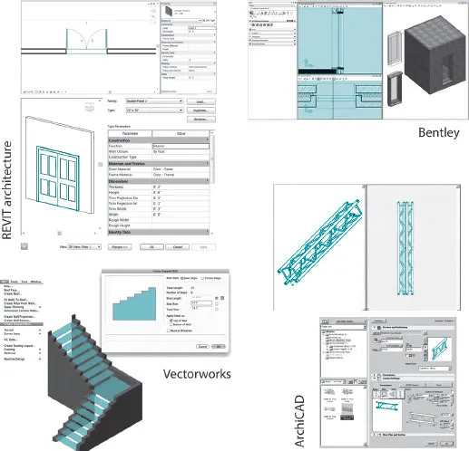
1.2 Parametric objects shown in four software programs (tha...