![]()
Section V
Advanced Materials and Technologies for Fuel Cells
![]()
12 | Advanced Materials for High-Temperature Solid Oxide Fuel Cells (SOFCs) Kuan-Zong Fung |
CONTENTS
12.1 | Introduction |
12.2 | Solid Electrolytes |
| 12.2.1 | Oxygen-Ion Conductors with Fluorite-Type Structure |
| | 12.2.1.1 | Doped Zirconia or Zirconium Oxide |
| | 12.2.1.2 | Ceria or Cerium Oxide |
| | 12.2.1.3 | Bismuth Oxide |
| 12.2.2 | Perovskite Structure |
| 12.2.3 | Proton Conductors |
| | 12.2.3.1 | Proton Conductors with Perovskite Structure |
12.3 | Anode of SOFCs |
| 12.3.1 | Requirements of Anode |
| 12.3.2 | Development of Anode Materials |
| | 12.3.2.1 | Conventional Ni–YSZ Cermet Anode Materials |
| | 12.3.2.2 | Other Cermet Anode Materials |
| 12.3.3 | Conducting Oxides |
| | 12.3.3.1 | Perovskite Anode Materials |
| | 12.3.3.2 | Pyrochlore Anode Materials |
| | 12.3.3.3 | Tungsten Bronze Anode Materials |
| 12.3.4 | Sulfur-Tolerant Anode Materials |
12.4 | Cathode |
| 12.4.1 | Category of the Cathode Material |
| | 12.4.1.1 | Perovskite-Type Structure Cathode Materials |
| | 12.4.1.2 | Ln1−xAxM1−yMnyO3-δ, Where Ln = La, Nd, Pr, etc., A = Ca, Sr, and M = Transition Metal |
| | 12.4.1.3 | Other Ln1−xAxM1−yMnyO3-δ |
| | 12.4.1.4 | La1−xSrxCoO3-δ |
| | 12.4.1.5 | La1−xSrxFe O3-δ |
| | 12.4.1.6 | La1−xSrxFe1−yCoyO3-δ |
| 12.4.2 | K2NiF4-Type Structure Cathode Materials |
| 12.4.3 | Ordered Double Perovskites |
| 12.4.4 | Surface Modification |
| | 12.4.4.1 | Mixed Ionic–Electronic Conductor (MIEC) |
| | 12.4.4.2 | Noble Particle Deposition on MIEC Cathode |
| | 12.4.4.3 | Thin Film Coating on MIEC Cathode |
| 12.4.5 | Summary |
12.5 | Interconnect |
| 12.5.1 | Ceramic-Based Interconnect |
| 12.5.2 | Metallic Interconnect |
| | 12.5.2.1 | Problems for Metallic Materials as Interconnect |
| | 12.5.2.2 | Excessive Growth and Spallation of Oxide Scale |
| | 12.5.2.3 | Chromium Poisoning |
| 12.5.3 | Contact Resistance of Metallic Interconnect |
| 12.5.4 | Materials for Metallic Interconnects |
| | 12.5.4.1 | Chromium-Based Alloys |
| | 12.5.4.2 | Fe–Cr-Based Alloys |
| | 12.5.4.3 | Ni–Cr-Based Alloys |
| 12.5.5 | Modification Coating |
| | 12.5.5.1 | Nitride Coatings |
| | 12.5.5.2 | Perovskite Coatings |
| | 12.5.5.3 | Spinel Coatings |
| 12.5.6 | Summary |
References |
12.1 INTRODUCTION
Among several types of fuel cells, the solid oxide fuel cell (SOFC) has shown advantages, such as high conversion efficiency, no need for noble metal catalysts, use of hydrocarbon fuel, no liquid in the fuel cell, etc. In recent years, a total of 10 MW Bloom Energy servers (100 kW per server) based on SOFC technology have been installed in California and North Carolina in the United States. The power generation of a 700-W unit of “Ene-Farm Type S,” which realized a power generation efficiency of 46.5% (net AC, LHV) as a commercially available residential-use fuel cell system, was developed jointly by Osaka Gas, Aisin Seiki, Kyocera, and Toyota Motor. Although the cost of an SOFC unit is still high, the future looks promising for SOFCs.
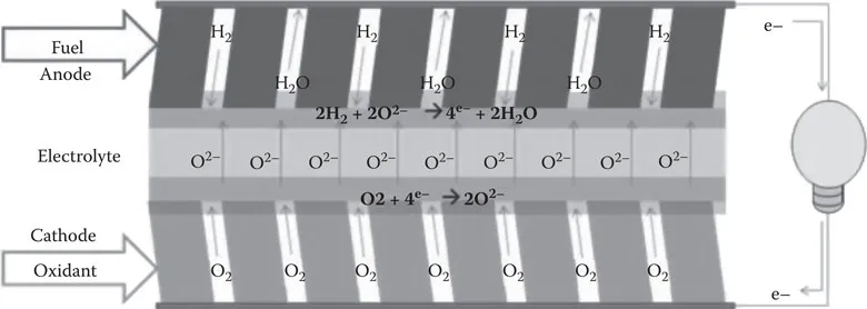
The major components of an SOFC are the solid electrolyte, the anode, and the cathode (see Figures 12.1 and 12.2). In addition, an interconnect is also needed when cells are arranged in series as a stack. Since each component is operated under a different environment, it must provide a different function and meet special requirements. For example, a solid electrolyte and an interconnect need to provide ionic conduction and electronic conduction, respectively. Both of them are separated by the fuel and the oxidant. Thus, they need to have adequate stability against oxidizing and reducing atmospheres. On the other hand, cathode and anode need to have ionic–electronic conduction in addition to adequate stability in either an oxidizing or a reducing environment.
FIGURE 12.1 Schematic diagram of the operating concept of an SOFC.
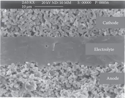
FIGURE 12.2 SOFC consists of two porous electrode layers and a dense electrolyte layer.
Fundamentally, the conductivity and stability of functional materials is strongly affected by their crystal structure and/or atomic arrangements. Therefore, in this chapter, some of the materials used in SOFCs are categorized on the basis of their unique crystal structures.
12.2 SOLID ELECTROLYTES
Solid electrolytes, namely solid-state ionic conductor, are materials that exhibit high ionic conduction (as high as 1 S cm−1) with negligible electronic conduction. The mobile ions involved in the electrochemical reaction of SOFCs are either oxygen ions (O2−) and/or protons (H+). Since ionic conduction in an ionic conductor is highly dependent on its defect concentration and crystals structure, oxygen-ion conductors used for SOFC electrolytes commonly have similar crystal structures, mainly fluorite- and perovskite-type structures.
12.2.1 OXYGEN-ION CONDUCTORS WITH FLUORITE-TYPE STRUCTURE
The cubic fluorite structure consists of relatively large oxygen ions that form 8-fold coordination. Every other cube is formed by the simple cubic packing of the oxygen ions having a cation at its center. On the basis of Pauling’s rules, the radius ratio Rcation/Ranion needs to be greater than 0.73. Oxides with CaF2 structure such as ZrO2, CeO2, and Bi2O3 have been extensively studied for the application.
12.2.1.1 Doped Zirconia or Zirconium Oxide
ZrO2 with proper dopant or stabilizer is the most common electrolyte used for SOFC applications. However, ZrO2 in its pure form cannot be used as a proper electrolyte because of its structural instability and low ionic conductivity. At temperatures from a melting point of 2680°C to 2370°C, undoped ZrO2 shows a cubic (c) structure. With further cooling down to 2370°C, the cubic phase will change to a tetragonal (t) form with slight distortion. As the temperature reaches 1170°C and below, the tetragonal ZrO2 exhibits a martensitic transformation into a monoclinic (m) form. The tetragonal–monoclinic transformation is accompanied with a large volume expansion (~5%) that may result in a catastrophic failure. Such a transformation may be rationalized by the undesired radius ratio of RZr+4/RO of well below 0.732. Thus, destabilization of the fluorite-structure ZrO2 is expected when the temperature is below 1170°C.
With proper addition of larger cations with lower valence, such as Y3+ and Ca2+, not only the radius ratio, Rcation/Ranion, is greater than 0.73, but also the positive oxygen vacancies are also created due to compensation of YZr or CaZr. Consequently, the cubic phase of doped ZrO2 may be stabilized to room temperature. In addition, the doped ZrO2 shows enhanced conduction of oxygen ions. Thus, 8 mol% Y2O3–stabilized ZrO2 (YSZ) is the mo...