![]()
PART I
Shells for architecture
![]()
CHAPTER ONE
Exploring shell forms
John Ochsendorf and Philippe Block
Shell structures will always have a role for architecture and engineering. More so than any other structural system, shells have the ability to create eye-catching forms, to provide freedom for design exploration and to resist loads efficiently. These attributes call for sustained interest in the mechanics and design of shell structures.
For even the most highly constrained geometry, an infinite number of solutions are availabel to the shell designer. But each different shell geometry has advantages and disadvantages, and all shells are not equal. How then does the designer find shell forms that are inherently structural? Shell designers can invent forms by taking inspiration from nature, by innovating from precedent structures, or by exploring various form-finding possibilities. In all cases, designers must seek forms that offer multiple load paths for all expected applied loads, and whose formal possibilities are closely linked to the modes of construction. Master shell builders are deeply concerned with the final appearance of their shells as well as the construction processes to create them.
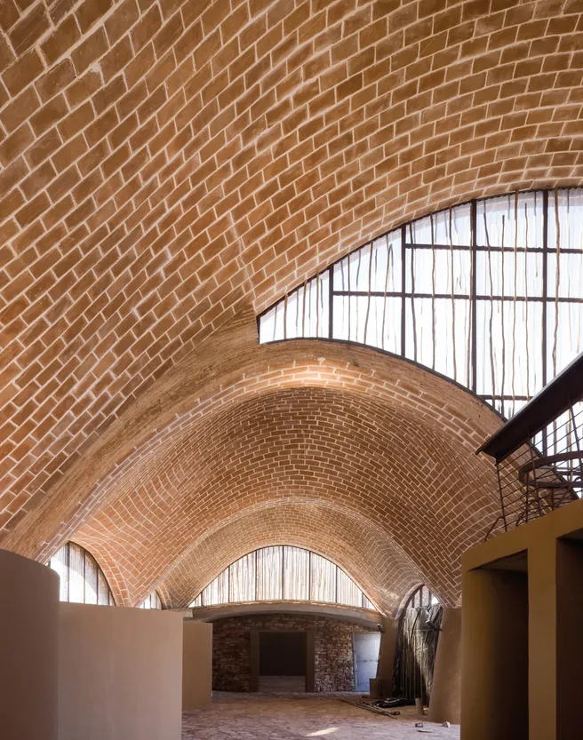
Designers can always learn more from studying historical structures and this is especially true of shells. Traditional masonry shells have a long history in architecture and construction, and the inherent limitations of masonry material require that such structures work primarily in compression. Recent buildings such as the Mapungubwe Interpretive Centre, with structural shells made from unreinforced earthen bricks, demonstrate the potential for contemporary projects to take inspiration from historical construction systems (see page 6).
1.1 Hooke’s hanging chain
The shell designer seeks forms to carry the applied loads in axial compression with minimal bending forces. The earliest example of structural form finding for an arch was published by English engineer and scientist Robert Hooke (1635–1703). In 1676, Hooke published ten ‘Inventions’ in the form of anagrams of Latin phrases in order to protect his ideas. The third invention would later become known as Hooke’s law of elasticity, for which he is most known.
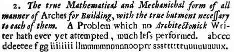
The second (Fig. 1.1), describing ‘the true Mathematical and Mechanichal form of all manner of arches for building’ is given as:
Figure 1.1 Robert Hooke’s anagram on the means to find the ideal compression-only geometry for a rigid arch (Hooke, 1676)
The solution to this architectonic riddle was posthumously published by the secretary of the Royal Society, Richard Waller (1705), and read:
Ut pendet continuum flexile, sic stabit contiguum rigidum inversum.
(As hangs the flexible line, so but inverted will stand the rigid arch.)
The idea is simple: invert the shape of the hanging chain, which by definition is in pure tension and free of bending, to obtain the equivalent arch that acts in pure compression.
The form of the ideal arch will depend on the applied loading. For a chain of constant weight per unit length, the shape of a hanging chain acting under self-weight is a catenary (Fig. 1.2). But if the load is uniformly distributed horizontally, the ideal arch would take the form of a parabola, and the chain would take different geometries according to the loading. In addition, the span/rise ratio (L/d) can vary widely, though most shell structures occur in the range of 2 < L/d < 10. Thus, even a simple two-dimensional arch has infinite possible forms which would act in pure compression under self-weight, depending on the distribution of weight and the rise of the arch.
This principle, which will be referred to in this book as ‘Hooke’s law of inversion’, can be extended beyond the single arch and considered for shell structures of various geometries. In the context of shell structures, the term funicular means ‘tension-only’ or ‘compression-only’ for a given loading, typically considered as the shape taken by a hanging chain for a given set of loads. Three-dimensional funicular systems are considerably more complex because of the multiple load paths that are possible. Unlike the case of a hanging cable with a single funicular form between its two supports, hanging membranes have multiple possible forms. And unlike the two-dimensional arch, the three-dimensional shell can carry a wide range of different loadings through membrane behaviour without introducing bending.
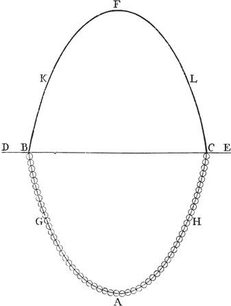
Figure 1.2 Hooke’s hanging chain and the inverted rigid catenary arch, as depicted by Poleni (1748)
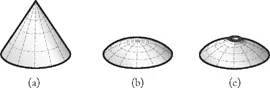
To continue the analogy with Hooke’s hanging chain, a three-dimensional model of intersecting chains could be created. This hanging model could be used to design a discrete shell, in which elements are connected at nodes, or the model could be used to help define a continuous surface. If hanging from a continuous circular support, the model-builder could create a network of meridional chains and hoop chains. By adjusting the length of each chain, various tension-only solutions can be found when hanging under self-weight only. Once inverted, this geometry would represent a compression-only form. Such a model would quickly illustrate that many different shell geometries can function in compression due to self-weight. As an example, Figure 1.3 illustrates three shell structures supported on a circular base: a cone, a shallow spherical dome and a dome with an upturned oculus in the centre. All three forms can contain compression-only solutions due to self-weight according to classical membrane theory (see Chapter 3). Of course some solutions perform better under varying load conditions and the double curvature of the dome is structurally superior to the single curvature of the cone in the event of asymmetrical live loading. Te conclusion is clear: for networks of intersecting elements, there is no unique funicular solution.
Figure 1.3 Examples of circular-plan shell structures which can act in pure compression under self-weight due to gravity: (a) conical shell; (b) shallow spherical dome; and (c) spherical dome with upturned oculus in centre
1.2 Masonry shells in compression
Masonry shells have been built for centuries around the world in the form of arches, domes and vaults. Such shells exist primarily in compression, because masonry materials such as brick and stone are strong in compression and weak in tension. Te challenge is to find geometries that can work entirely in compression under gravity loading. These geometries are not limited only to masonry, and will often provide efficient geometries for structures built of any material. However, for traditional masonry structures, the dominant loading is often due to the self-weight of the structure, and the applied live loadings due to wind or snow have a smaller effect.
As a practical demonstration of the multiple compressive solutions in three dimensions, consider the wide variety of shell geometries constructed in masonry tile commonly known as the Catalan vault or Guastavino method of construction. Compression-only tile vaults supported on a circular plan can take many possible geometries, ranging from conical to spherical as demonstrated by the structures in Figure 1.4. Even in brittle masonry structures, numerous openings can be made in shells and the resulting compr...