![]()
Part II
Contemporary HPC
![]()
Chapter 4
Tera 100
Mickaël Amiet, Patrick Carribault, Elisabeth Charon, Guillaume Colin de Verdière, Philippe Deniel, Gilles Grospellier, Guénolé Harel, François Jollet, Jacques-Charles Lafoucrière, Jacques-Bernard Lekien, Stéphane Mathieu, Marc Pérache, Jean-Christophe Weill, and Gilles Wiber
CEA, DAM, DIF
4.1 Overview
4.1.1 Sponsor/Program Background
4.1.2 Timeline
4.2 Applications and Workloads
4.2.1 Highlights of Main Applications
4.2.2 Benchmark Results
4.3 System Overview
4.4 Hardware Architecture
4.5 System Software
4.5.1 Open Source Software: A New Way of Conducting Industrial Collaboration
4.5.1.1 RobinHood Policy Engine
4.5.1.2 NFS-Ganesha
4.5.2 ClusterShell and Shine
4.5.2.1 ClusterShell
4.5.2.2 Shine
4.6 Programming System
4.6.1 Tera 100 Parallel Programming Models
4.6.2 Tera 100’s Programming Languages
4.6.3 Tera 100’s Frameworks
4.6.4 Tera 100’s Libraries
4.6.4.1 Hercule
4.6.5 Tools
4.7 Storage, Visualization, and Analytics
4.7.1 ST100 and GL100, Two Sides of Tera 100’s Storage
4.7.1.1 ST100: Hierarchical Storage Management to Mix Disks and Tapes inside a Very Capacitive Storage System
4.7.1.2 GL100: Using a High-Performances Storage System as a Front-End to Storage System
4.7.1.3 Making ST100 and GL100 Work in an Aggressively Cooperative Way
4.7.2 Visualization
4.8 Data Center and Facility
4.8.1 Tera 100: A Large Technical Facility
4.8.1.1 Tera Building
4.8.1.2 Electricity Distribution
4.8.1.3 Cooling System
4.8.1.4 Security System
4.8.2 Tera 100: Energy Issue
4.8.2.1 Electricity Consumption Reduction for IT Equipment
4.8.2.2 A More Effective Cooling System
4.8.2.3 A Passive Device to Reduce UPS Usage
4.9 System Statistics
4.9.1 Tera Computing Center: Control and Analysis of the Functioning
4.9.1.1 Tera 100, the High Performance Computer
4.9.1.2 Control of Availability and Utilization of the Computer
4.9.1.3 Profiling the Usage
4.9.1.4 Control of the Activity on Parallel Filesystems
4.9.2 Hardware Reports
4.9.2.1 Electrical Consumption Supervision
4.9.2.2 The Storage System
4.10 Looking Forward
4.10.1 The Tera “Family”
4.10.2 En Route to the Future
4.1 Overview
4.1.1 Sponsor/Program Background
The Tera 100 is the third machine of the Tera program implemented by CEA/DAM. CEA/DAM is a division of CEA (Commissariat à l’énergie atomique et aux énergies alternatives, Direction des Applications Militaires) in charge of building the French Deterrence.
Since the late fifties, France has had a research program to develop nuclear warheads. This program has always used numerical simulation. In 1992, French President Francois Mitterrand decided on a moratorium on nuclear testing which increased the use of HPC at CEA/ DAM. In 1996, after a last test campaign, President Jacques Chirac decreed the end of French nuclear tests and the start of the simulation program. This program is based on large physics instruments like the “Laser Mégajoule” or the radiography facility “AIRIX” and on numerical simulation. The objective was to increase by a factor of 20,000 the computing power available to CEA/DAM.
The Tera program started as early as 1996, when France decided to end its nuclear tests and design and guarantee its deterrence through simulation. More than 15 years ago, CEA realized that, in order to fulfill our mission, we needed to deliver to our users a petaflop class machine by 2010.
This computing power was achieved in three steps, ×100 in 2001 (Tera 1), ×1,000 in 2005 (Tera 10), ×25,000 in 2010 (Tera 100), to get a petaflop system. The three Tera systems are based on the same architecture: cluster of commodity servers with a high performance interconnect and an increasing use of open source technologies. These three systems are also large data producers and consumers: Tera 1 needed 7.5 GB/s, Tera 10 100 GB/s, and Tera 100 a mere 500 GB/s.
Tera 1 was a major shift from a long tradition of CRAY vector machines which ended with a CRAY T90. To build Tera 1, we changed our design requirements from using highly efficient proprietary components to using COTS.1 This introduced the CEA developers to the world of massive parallelism. Designed by Compaq (then maintained by HP), Tera 1 used the famous Alpha processor with a special Quadrics Elan 3 interconnect.
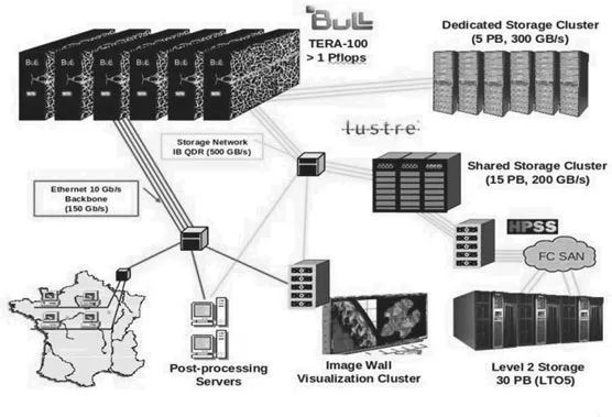
FIGURE 4.1: Architecture of the Tera facility.
Designed by BULL, Tera 10 capitalized on Tera 1 lessons and kept the same architecture (a cluster of SMP using the Quadrics Elan 4 interconnect) while moving to Intel’s Itanium processor. It was a very stable machine with a high level of productivity. At this step we started using the Lustre filesystem (Figure 4.1).
Tera 100, also designed by BULL, pushed the design even further in relying on the ubiquitous x86 64 architecture, thus providing a seamless environment to our users from the desktop to the supercomputer. We also shifted from the Quadrics interconnect to InfiniBand, which will be described in a later section. A comparison of the Tera machines can be found in Figure 4.5.
Tera 100 is an exceptional general purpose computer, designed for classified workloads coming from various CEA/DAM laboratories. This machine demonstrates unique capabilities as we will show.
4.1.2 Timeline
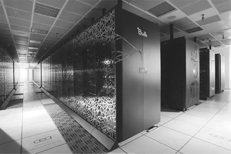
The third step of the simulation program, Tera 100 (Figure 4.2) could not be achieved by the natural evolution of HPC (Moore’s law). In particular the new system had to use the same computer room as the Tera 1 system, so it had to be much more dense than what we could expect from the HPC market. The density, the I/O needs, and the efficiency required by CEA/DAM simulation chain brought us to start in 2008 a new way of procurement for this system. For Tera 1 and Tera 10, we made classical RFP for a system; for Tera 100 the project team made an RFP for a shared research program and the machine was an option of this contract which would be exercised if and only if the research program was successful.
The research program started in 2008 and ran for two years. It covered all the aspects of an HPC system used for large production. The main results are:
• a cooling rack based on cold water able to cool up to 40 KW;
• a high density 4 socket Xeon Nehalem server (8 sockets in 3 U);
• a high density 2 socket Xeon Nehalem blade server and a flexible chassis;
FIGURE 4.2: Tera 100. (©P. Stroppa/CEA.)
• a new server power distribution based on a capacitor allowing up to 500 ms of electrical power loss;
• a petaflop cluster software stack;
• an InfiniBand topology based on fat-tree islands.
After 18 months of research a prototype system was delivered at CEA. This prototype allowed CEA teams to validate the computer room integration, the software stack, and the hardware technologies. The prototype had a computing power close to the Tera 10 system and was stable enough to allow a successful port of main CEA/DAM codes on the new platform. This success prompted CEA to order the final configuration.
The new cooling system based on cold water injected in the rack door (see Figure 4.17) introduced major changes in the computer room:
• many large pipes had to be installed under the raised floor to bring a water loop to each rack;
• all the power distribution had to be removed from the raised floor and be redone from the ceiling;
• an increase of 6 MW in power distribution was needed.
Tera 100 was installed from March 2010 to September 2010. The best Linpack run happened on October 12th (see the benchmark section). The machine was ranked as the first machine in Europe in 2010 and the 6th machine of the TOP500 list. After a few weeks of grand challenge computations, the system moved to production in early 2011. The Tera 10 machine was decommissioned on July 2011.
4.2 Applications and Workloads
As previously stated, Tera 100 is a general purpose computer which handles both production runs for the designers as well as more research-oriented ones conducted by our physicists. This means that the machine, by design, is able to run a wealth of different codes. The spectrum ranges from multimillion lines of C + +/FORTRAN multi-physics hydro codes to small C + + programs intended to investigate some highly specialized aspects of physics or chemistry.
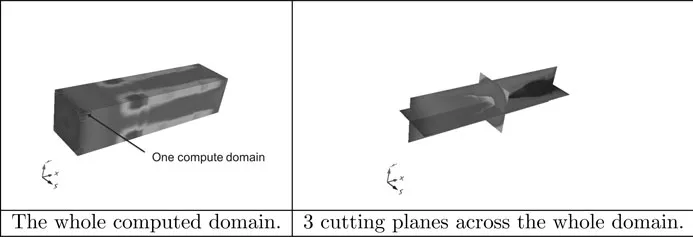
FIGURE 4.3: Example of a 4-billion cell computation done on 4096 cores of Tera 100, visualized using our LOVE package.
All the codes are able to run in parallel yet some are less scalable than others. A simulation can span on for multiple weeks if not months. Therefore, it is allowed to run typically by slots of 10 hours monitored by an in-house meta scheduler (called KMS).
The numerous codes cover a variety of fields. The following list is only part of them:
• Nuclear Physics: With our codes, we fully simulate a nuclear weapon.
• Laser Physics: These codes are essential tools to predict and do the interpretation of the experiments we will conduct in our facility called the “Laser Mégajoule” located near Bordeaux. This unique installation requires the most advanced simulation codes to understand the extreme conditions taking place during the experiments.
• Material Sciences: For its mission, CEA uses various materials which have strange physical properties in the long run. To understand the behavior of matter, we have developed codes to peek at the lowest level of matter (at the atom level and beyond). Some of the codes are developed in collaboration with universities, as in the case of ABINIT, which we will describe in the next section.
• Engineering: FLUENT, ABAQUS, and other commercial packages are used to study the properties of the objects manufactured by CEA/DAM.
• Earth Science: Through knowledge gained from underground tests, CEA/DAM has harvested a unique expertise in geosciences which is now used in homeland security projects such as CENALT (CENtre d’Alerte aux Tsunamis). For this mission, highly efficient and predictive codes are needed.
• Post-processing and Visualization: Such a large machine as Tera 100 allows for the largest simulations. We had to develop a visualization system able to cope with the multi-terabyte data set produced by our record-breaking I/O subsystem. This is the LOVE2 environment bu...