Steel Design covers steel design fundamentals for architects and engineers, such as tension elements, flexural elements, shear and torsion, compression elements, connections, and lateral design. As part of the Architect's Guidebooks to Structures series it provides a comprehensive overview using both imperial and metric units of measurement. Each chapter includes design steps, rules of thumb, and design examples. This book is meant for both professionals and for students taking structures courses or comprehensive studies. As a compact summary of key ideas, it is ideal for anyone needing a quick guide to steel design. More than 150 black and white images are included.
eBook - ePub
Steel Design
- 312 pages
- English
- ePUB (mobile friendly)
- Available on iOS & Android
eBook - ePub
About this book
Trusted by 375,005 students
Access to over 1.5 million titles for a fair monthly price.
Study more efficiently using our study tools.
Information
Topic
ArchitectureSubtopic
Architecture GeneralChapter 1
LeBow Business Building
1.1 Introduction
1.2 Design Development
1.3 Construction Documents
1.4 Construction Administration
1.5 Opening

Figure 1.1 LeBow Building
Source: Keast & Hood
The construction of any significant work requires hard work both intellectually and physically. Honesty, adaptability, and attention to detail help also. The LeBow School of Business is a case in point. From its outset, the project was a challenge to the entire team. The only predictable outcome was that a new building would be constructed. Its appearance, size, shape, and final cost would be determined by those who would mold the clay that started as an idea, and finished with an opening that belied the struggle we all went through to see it completed.
1.1 Introduction
Bennett LeBow is a Drexel University Graduate and a Philadelphia native. His generosity provided the major funding necessary to construct the LeBow College of Business. When the project was announced, several well-known architects competed for the commission. The winning team was Robert A. M Stern with Voith-MacTavish Architects.
The proposed site was occupied by Matheson Hall, a depressing, four-story, 60s-style structure facing Market Street. Before Matheson was constructed, row houses and small buildings lined both Woodland Avenue and Market Streets.
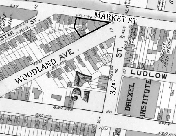
Figure 1.2 West Philadelphia c. 1895, showing building site names annotated
Source: Philageohistory.org
Incorporating Matheson Hall was an early goal but its restrictive headroom, shallow basement, narrow bays, and small foundations limited the new design. Reinforcing the structure and living with the existing column grid would negate any savings and compromise the program. Matheson had to go.
About 30 ft (9.1 m) below Market Street is Philadelphia’s main east–west commuter line, the Market–Frankford EL (elevated). This subterranean structure presented challenges but helped in other ways as will be discussed. Other non-yielding site features included public utilities within the Market and Woodland Avenue rights of way. Taken together, these restrictions defined a tight triangular property, shown in Figure 1.2.
Reflecting the site, a triangular plan evolved with symmetry about the long bisector. The two long sides or “bars” define a central, 7-story-high atrium. The shortest bar is the tallest at 12 stories and houses faculty offices and classrooms. The other two bars are about half as high at 7 stories each and support classrooms, large meeting rooms, and a very large, lower level auditorium.
1.2 Design Development
With an aggressive schedule and many unknowns, a steel frame was the logical choice for its inherent strength and design flexibility. Steel costs were disproportionately high and the structural engineers looked for savings. After the initial modeling was complete, the steel weighed-in at approximately 18 psf, including columns. This was too heavy so we explored ways to reduce the weight. Some of this high weight was attributable to wide bays, initial conservatism, and an excessive number of heavy column transfers required by floor plan alignment (or misalignment) between levels.
Value Engineering (VE), often bemoaned by design teams, is a CM-driven process to identify potential savings used to meet a construction budget. On LeBow, VE offered difficult choices. One of the least palatable was to shell some of the tower office levels pending added funding for fit-out (shell means build the space without finishes).
Motivated by the cost pressure, the architects reworked the plans to better align walls (and columns) between floors. Some column transfers were inevitable, such as those above the large subterranean auditorium. We worked on reducing our initial conservatism on the structure.
Other challenges that surfaced were below grade. Based on groundwater observation wells, the geotechnical engineer recommended we design for 8 feet (2.44 m) of hydrostatic pressure beneath the lower level. This impacted the site development costs and drove the design decision to use a mat foundation system acting as a very large boat. A blessing in disguise, the Market Street subway with its own system of drains, helped lower the groundwater by acting as a large French drain during construction.
Our solution for spanning over the lower level auditorium was to design story-high trusses extending from the 2nd to the 3rd floors to be concealed behind the atrium walls (Figure 1.3). Temporary columns supported the first, second, and third floor framing until the trusses were built and stabilized. The columns between levels one and two, below the trusses, were initially in compression but became hangers after the trusses were put into service.
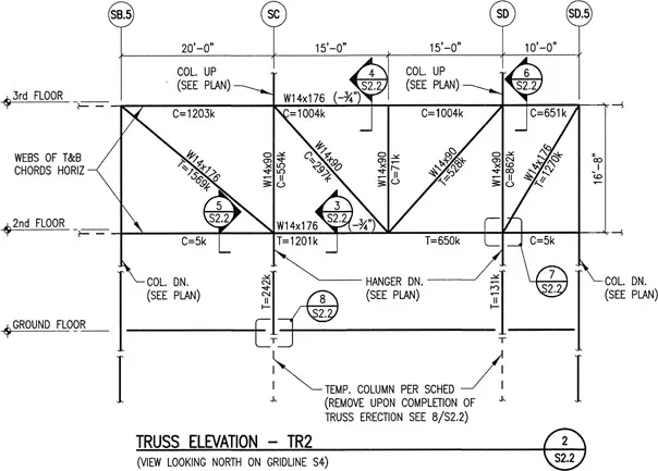
Figure 1.3 Truss TR-2 Elevation
Source: Keast & Hood
The trusses above the auditorium were modeled in STAAD® as simply supported plane trusses with one top chord support pinned and the other on a roller. The bottom chords were modeled with roller or slide supports.
Cantilevers, another device used to convey weightlessness, spawned the question “how thin can you make it?” As the engineers for many architecturally driven projects, we try hard to provide an economical solution but are mindful of the architects’ wishes. This came into play on the eastern façade where we absorbed the structure into the slab, saving 5 in (127 mm) of depth, shown in Figure 1.5. This was at no small cost from an engineering and construction standpoint, but was important architecturally.
At the northwest corner adjacent to Market Street, a cantilevered corner was structured with a large diagonal rod that would remain visible behind the aluminum curtain wall and became a design feature, shown in Figure 1.6. We cantilevered orthogonal W24 × 104 from the nearest point on line N1 to provide needed redundancy and stability during erection until the 2 in (51 mm)-diameter diagonal rod was installed and tensioned.
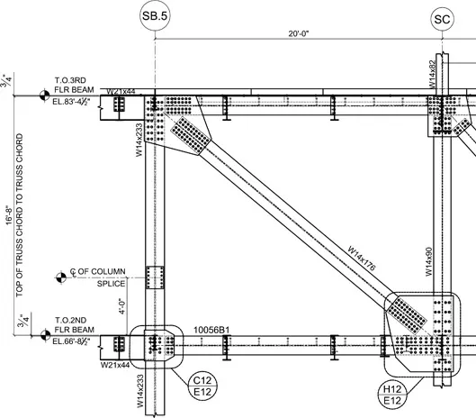
Figure 1.4 Truss TR-2 Column Connections
Source: Keast & Hood
Resisting lateral loads presented a larger challenge. Surrounding the elevator and stair core and rising some 250 ft (46 m) above the foundations, the tower had its own diagonally braced core. Because the building was to be relatively long in the east–west direction, the broader 7-story section off to the east demanded a lateral system of its own. For that, we designed concrete shear walls around the easternmost stair rising 7 stories.
The two bracing systems responded very differently. In our model; the steel core bracing acted as a tall-cantilevered truss and the shear walls as squat, rigid elements of the structure. The shear walls attracted tremendous forces from the tower bracing system. Rather than separating the two systems with an expansion joint, as would be required in a high seismic area, we decided to join them with drag struts at the 5th and 6th floors.
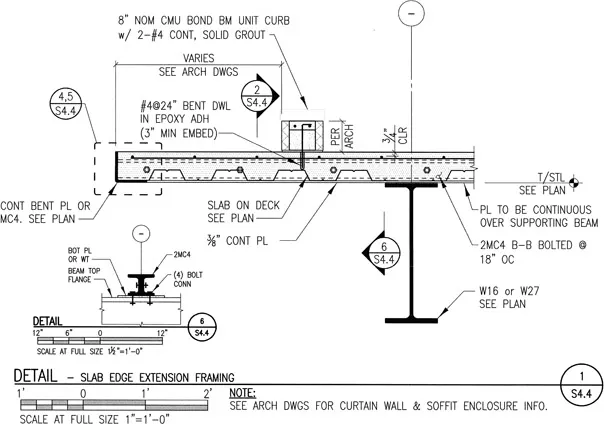
Figure 1.5 Slab Extension
Source: Keast & Hood
With the potential of large temperature swings during construction, we were also concerned that thermal forces might overstress the drag struts. If restrained against shrinkage or expansion, steel and concrete can overwhelm connections to supports. Bridge designers know this well and therefore connect one end of bridges on roller supports so the structure can “breathe” with seasonal temperature changes.
Façade elements were another challenge. Panel weights and restrictive deflection limitations forced the spandrel beams to be very heavy. The architectural precast wall panels were designed as 8-foot (2.44 m) wide, 2-story tall elements imposing their weight eccentrically on spandrel beams. We designed rotation counters perpendicular to these spandrel beams but our assumed eccentricity of 6 in (152 mm) to the precast load was not enough. When the shop drawings arrived, we saw they had between 8 and 10 in (203 and 254 mm) of eccentricity and the loads did not align well with the rotational restraint of the beams.
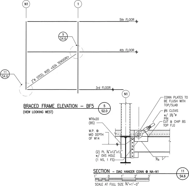
Figure 1.6 N-W Corner Diagonal Brace
Source: Keast & Hood
In hindsight, we might have been better off with structural tubes as spandrel beams or plating one side of the wide flange members to add torsional strength and rigidity. The fix was field installation of diagonal kickers at precast connection locations not backed up by a torsional restraint beam.
Another challenge we faced was with the glass curtain wall contractor who wanted to “panelize” his system to expedite erection and decrease labor costs. The architecture did not permit topside connections to the slab so the connections were hidden below. This under-slab connection suggested by the envelope consultant and designed by the curtain wall...
Table of contents
- Cover
- Title
- Copyright
- Dedication
- Contents
- Acknowledgments
- Notes on Contributors
- Introduction
- 1 LeBow Business Building
- 2 Steel Fundamentals
- 3 Steel Tension
- 4 Steel Bending
- 5 Steel Shear and Torsion
- 6 Steel Compression
- 7 Steel Lateral Design
- 8 Steel Connections
- Appendix 1: Selected Section Properties
- Appendix 2: Beam Solutions
- Appendix 3: Units
- Appendix 4: Symbols
- Appendix 5: Units Conversion
- Bibliography
- Glossary
- Index
Frequently asked questions
Yes, you can cancel anytime from the Subscription tab in your account settings on the Perlego website. Your subscription will stay active until the end of your current billing period. Learn how to cancel your subscription
No, books cannot be downloaded as external files, such as PDFs, for use outside of Perlego. However, you can download books within the Perlego app for offline reading on mobile or tablet. Learn how to download books offline
Perlego offers two plans: Essential and Complete
- Essential is ideal for learners and professionals who enjoy exploring a wide range of subjects. Access the Essential Library with 800,000+ trusted titles and best-sellers across business, personal growth, and the humanities. Includes unlimited reading time and Standard Read Aloud voice.
- Complete: Perfect for advanced learners and researchers needing full, unrestricted access. Unlock 1.5M+ books across hundreds of subjects, including academic and specialized titles. The Complete Plan also includes advanced features like Premium Read Aloud and Research Assistant.
We are an online textbook subscription service, where you can get access to an entire online library for less than the price of a single book per month. With over 1.5 million books across 990+ topics, we’ve got you covered! Learn about our mission
Look out for the read-aloud symbol on your next book to see if you can listen to it. The read-aloud tool reads text aloud for you, highlighting the text as it is being read. You can pause it, speed it up and slow it down. Learn more about Read Aloud
Yes! You can use the Perlego app on both iOS and Android devices to read anytime, anywhere — even offline. Perfect for commutes or when you’re on the go.
Please note we cannot support devices running on iOS 13 and Android 7 or earlier. Learn more about using the app
Please note we cannot support devices running on iOS 13 and Android 7 or earlier. Learn more about using the app
Yes, you can access Steel Design by Paul McMullin, Jonathan Price, Richard Seelos, Paul McMullin,Jonathan Price,Richard Seelos, Paul W. McMullin, Jonathan S. Price, Richard T. Seelos in PDF and/or ePUB format, as well as other popular books in Architecture & Architecture General. We have over 1.5 million books available in our catalogue for you to explore.