![]()
1.0 Introduction to Outrigger Systems
1.0 Introduction to Outrigger Systems
1.1 Background
Outriggers are rigid horizontal structures designed to improve building overturning stiffness and strength by connecting the building core or spine to distant columns. Outriggers have been used in tall, narrow buildings for nearly half a century, but the design principle has been used for millennia. The oldest “outriggers” are horizontal beams connecting the main canoe-shaped hulls of Polynesian oceangoing boats to outer stabilizing floats or “amas” (see Figure 1.1). A rustic contemporary version of this vessel type illustrates key points about building outrigger systems:
►A narrow boat hull can capsize or overturn when tossed by unexpected waves, but a small amount of ama flotation (upward resistance) or weight (downward resistance) acting through outrigger leverage is sufficient to avoid overturning. In the same manner, building outriggers connected to perimeter columns capable of resisting upward and downward forces can greatly improve the building’s overturning resistance.
►Even though a boat may be ballasted to resist overturning it can still experience uncomfortable long-period roll, outrigger-connected amas greatly reduce that behavior and shorten the period of the movement. Similarly, building outriggers can greatly reduce overall lateral drift, story drifts, and building periods.
►Boats can have outriggers and amas on both sides or on one side. Buildings can have a centrally located core with outriggers extending to both sides or a core located on one side of the building with outriggers extending to building columns on the opposite side.
The explanation of building outrigger behavior is simple: because outriggers act as stiff arms engaging outer columns, when a central core tries to tilt, its rotation at the outrigger level induces a tension-compression couple in the outer columns acting in opposition to that movement. The result is a type of restoring moment acting on the core at that level.
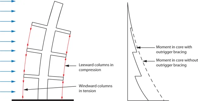
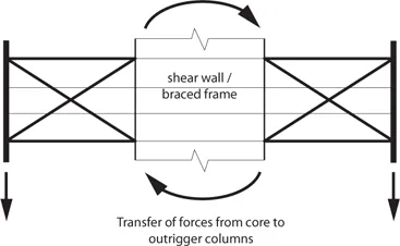
Analysis and design of a complete core-and-outrigger system is not that simple: distribution of forces between the core and the outrigger system depends on the relative stiffness of each element. One cannot arbitrarily assign overturning forces to the core and the outrigger columns. However, it is certain that bringing perimeter structural elements together with the core as one lateral load resisting system will reduce core overturning moment, but not core horizontal story shear forces (see Figures 1.2 & 1.3). In fact, shear in the core can actually increase (and change direction) at outrigger stories due to the outrigger horizontal force couples acting on it.
Belts, such as trusses or walls encircling the building, add further complexity. Belts can improve lateral system efficiency. For towers with outriggers engaging individual mega column, belts can direct more gravity load to the mega columns to minimize net uplift, reinforcement or the column splices required to resist tension and stiffness reduction associated with concrete in net tension. For towers with external tube systems — closely spaced perimeter columns linked by spandrel beams — belts reduce the shear lags effect of the external tube, more effectively engage axial stiffness contributions of multiple columns, and more evenly distribute across multiple columns the large vertical forces applied by outriggers. For both mega column and tube buildings, belts can further enhance overall building stiffness through virtual or indirect outrigger behavior provided by high in-plane shear stiffness (discussed later), as well as increasing tower torsional stiffness. Belts working with mega columns can also create a secondary lateral load resisting system, in seismic engineering terminology.
▲Figure 1.1: Samoan outrigger canoe. © Teinesavaii.
▲Figure 1.2: Interaction of core and outriggers.(Source: Taranath 1998)
▲Figure 1.3: Outrigger at core.(Source: Nair 1998)
A core-and-outrigger system is frequently selected for the lateral load resisting system of tall or slender buildings where overturning moment is large compared to shear, and where overall building flexural deformations are major contributors to lateral deflections such as story drift. In such situations, outriggers reduce building drift and core wind moments. Because of the increased stiffness they provide, outrigger systems are very efficient and cost-effective solutions to reduce building accelerations, which improves occupant comfort during high winds (Po & Siahaan 2001).
1.2 Benefits of an Outrigger System
Deformation Reduction
In a building with a central core braced frame or shear walls, an outrigger system engages perimeter columns to efficiently reduce building deformations from overturning moments and the resulting lateral displacements at upper floors. A tall building structure which incorporates an outrigger system can experience a reduction in core overturning moment up to 40% compared to a free cantilever, as well as a significant reduction in drift depending on the relative rigidities of the core and the outrigger system (Lame 2008). For supertall towers with perimeter mega columns sized for drift control, reduction in core overturning can be up to 60%. The system works by applying forces on the core that partially counteract rotations from overturning. These forces are provided by perimeter columns and delivered to the core through direct outrigger trusses or walls, or indirect or “virtual” outrigger action from belt trusses and diaphragms as described in Section 3.6.
Efficiency
For systems with belt trusses that engage all perimeter columns, columns already sized for gravity load may be capable of resisting outrigger forces with minimal changes in size or reinforcement, as different load factors apply to design combinations with and without lateral loads. In the event that additional overall flexural stiffness is required, the greater lever arm at outrigger columns makes additional material more effective than in the core. Outriggers may also permit optimization of the overall building system using techniques such as the unit load method to identify the best locations for additional material (Wada 1990). By significantly decreasing the fraction of building overturning moment that must be resisted by the core, wall, or column material quantities in the core can be reduced while outrigger, perimeter belt, and column quantities are increased by a smaller amount. Lower limits on core required strength and stiffness may be defined by story shears resisted by the core alone between outrigger levels, special loading conditions that exist at outrigger stories, or short-term capacity and stability if outrigger connections are delayed during construction
Foundation Forces
A separate but related advantage is force reduction at core foundations. Outrigger systems help to effectively distribute overturning loads on foundations. Even where a foundation mat is extended over the full tower footprint, a core-only lateral system applying large local forces from overturning can generate such large mat shear and flexural demands, as well as net tension in piles or loss of bearing, that the design becomes uneconomical or impractical. Reducing core overturning and involving perimeter column axial forces to help resist overturning from lateral loads reduces mat shear demand, flexural demand, and net uplift conditions by spreading loads from overturning across the tower footprint. Reducing variations in sub-grade stresses or pile loads under the core from lateral load will reduce foundation rotations that can contribute to overall and inter-story drifts. Having an outrigger system may or may not change other aspects of the foundation design, such as governing pile loads and footing or mat bearing pressures. They must be checked for all relevant load combinations, as combinations for gravity loads may govern over combinations including lateral loads.
Gravity Force Transfers
Outriggers and belt trusses can help reduce differential vertical shortening between columns, or between a column and the core. This can reduce floor slopes between those elements which may occur from creep, shrinkage, or thermal changes. The reduction is achieved by force transfers between adjacent columns through belt trusses, or between the columns and core through outriggers. This is a secondary benefit at best, and is a two-edged sword: force transfers can become quite large — potentially comparable in magnitude to forces from overturning resistance — and costly to achieve. Balancing potential benefits and costs requires a solid understanding of the phenomenon as well as proper application of details and construction strategies to manage its effects. Force determination and control is discussed later in the text.
Outriggers are rigid horizontal structures designed to improve building overturning stiffness and strength by connecting the building core or spine to distant columns.
Torsional Stiffness
Belt trusses can provide a different secondary benefit: improved torsional stiffness. A core-only tower can have low torsional stiffness compared to a perimeter-framed tower, due to the much smaller distance between resisting elements. A core-and-outrigger building can have similarly low torsional stiffness. Belt trusses can force perimeter columns to act as fibers of a perimeter tube that, while not as stiff as a continuous framed tube, still provides significant additional torsional stiffness.
Disproportionate Collapse Resistance
Another potential benefit related to force transfer capability is disproportionate (progressive) collapse resistance. On projects which require considering sudden loss of local member or connection capacity, outriggers can provide alternate load paths. For example, where perimeter columns are engaged by belt trusses, loads from floors above a failed perimeter column could “hang” from the upper column acting in tension and then be transferred through upper belt trusses to adjacent undamaged columns. Where outriggers are present without belt trusses, it may be possible to hang upper floor loads from outriggers which load the core, but massive outrigger columns may be too heavily loaded for this load path to be practical. In a braced-frame-core building, loads from floors above a failed core column could be shared by perimeter members through outriggers. Of course the design must be checked to confirm that alternate load paths can accept the resulting forces rather than leading to further failures. For disproportionate collapse checks load factors are often smaller and capacities considered are often larger than those used for the basic design, so the effect of these conditions on the building design may be minimal, depending on the scenarios considered.
For example, 300 Madison Avenue, New York City (2003) is of moderate height (35 stories / 163 meters) but includes belt trusses at floors 9 through 11 and above 35 as indirect or virtual outriggers to reduce overturning on the slender core, improve torsional stiffness, and provide alternate load paths in case of perimeter column damage (Arbitrio & Chen 2005; Chen & Axmann 2003).
Architectural Flexibility
Core-and-outrigger systems permit design variations in exterior column spacing to satisfy aesthetic goals and, in some cases, specific functional requirements. Internal or direct outriggers need not affect the building’s perimeter framing or appearance compared with other floors. Supertall buildings with outriggers may have a few exterior mega columns on each face, which opens up the fagade system for flexible aesthetic and architectural expression. This overcomes a primary disadvantage of closed-form tubular systems used in tall buildings. The quantity and location of mega columns have impacts on typical floor framing, plans featuring...