Timber Design covers timber fundamentals for students and professional architects and engineers, such as tension elements, flexural elements, shear and torsion, compression elements, connections, and lateral design. As part of the Architect's Guidebooks to Structures series, it provides a comprehensive overview using both imperial and metric units of measurement. Timber Design begins with an intriguing case study and uses a range of examples and visual aids, including more than 200 figures, to illustrate key concepts. As a compact summary of fundamental ideas, it is ideal for anyone needing a quick guide to timber design.
- 370 pages
- English
- ePUB (mobile friendly)
- Available on iOS & Android
eBook - ePub
Timber Design
About this book
Trusted by 375,005 students
Access to over 1.5 million titles for a fair monthly price.
Study more efficiently using our study tools.
Information
Chapter 1
Merion Friends Meetinghouse
1.1 Introduction
1.2 Historical Overview
1.3 Building Description
1.4 Survey and Assessment
1.5 Analysis
1.6 Structural Strengthening
1.7 A New Plan
1.8 Lessons Learned
1.1 Introduction
Merion Friends Meetinghouse, shown in Figure 1.1, is located in southeastern Pennsylvania and is the oldest Quaker meetinghouse in the state. It is the second oldest in the U.S., eclipsed in age by the Third Haven Meetinghouse in Easton, Maryland (c. 1682). It was a religious and community center for centuries and is still used today.
1.2 Historical Overview
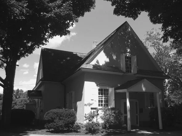
Figure 1.1 Merion Friends Meetinghouse, front entrance
Source: Photo courtesy of Keast & Hood
The Merion settlement was on land given to young William Penn by King Charles II. Penn received this land as repayment of a loan Penn’s father had given to the king in 1660 so that England could rebuild its navy. This was a win–win for the king, who now could get rid of the troublesome Quakers and pay off a substantial debt. For William Penn, this was an opportunity to realize his dream of planting “the seed of a nation,” reflecting Quaker ideals in the New World.1 In 1682, the first group of Quakers from Merionethshire, Wales, settled near Philadelphia and, in 1695, they began construction of the meetinghouse.2 Although the land was given to Penn by the king, he paid the Native Americans £1,200 for it, rather than take it through conquest.3
1.3 Building Description
The meetinghouse is a modest structure and is nontraditional because of its T-shaped plan, as most meetinghouses are rectangular. Because Merion has two ridgelines meeting at a rather central point, there are valleys that allow accumulations of leaf debris, making the roof susceptible to leaks.
The roof frames are Welsh-influenced cruck-type frames supported on 24-in-thick stone walls, and these frames resemble A-frames. They have truss elements, which were intended to support the original high ceiling and perhaps restrain outward thrust. The low ceiling was added in 1829 (ref. Figure 1.2 and longitudinal section of Figure 1.3).
Some believe that the southern portion (stem of the tee) was constructed first, with the northern section an addition. No evidence has been found to support this theory, such as remnants of an old foundation in the crawl space. Also, the north section center frame was tenoned into the first frame of the south section, and so it must have followed soon after the south (Figure 1.4).4
Before the meetinghouse was nominated to the National Historic Register, it attracted attention. In 1981, noted historian David Yeomans wrote:
The most interesting roof to have been found in this area [i.e., Pennsylvania, New Jersey, and Delaware] is that of Merion Meetinghouse because this structure uses a primitive form of trussing I have not so far seen in England, although it clearly derives from there. The principal rafters curve downward sharply at their feet—a feature shown in the earliest published drawing of a roof structure. The tie beams are trussed up with timbers that are not quite king posts in that they are not hung from the apex of the roof. No metal strapping is used and instead the post is fixed to the tie beam with a dovetail.5
Ideally, the original curved frame pieces would have been sawn from trees with large sweeping branches, so that the grain and stresses could have followed the curve. Instead, they used large sections of straight
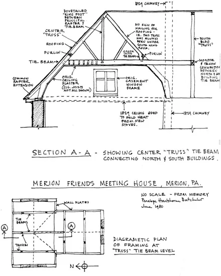
Figure 1.2 Unpublished survey drawings by Penny Batcheler, c. 1980
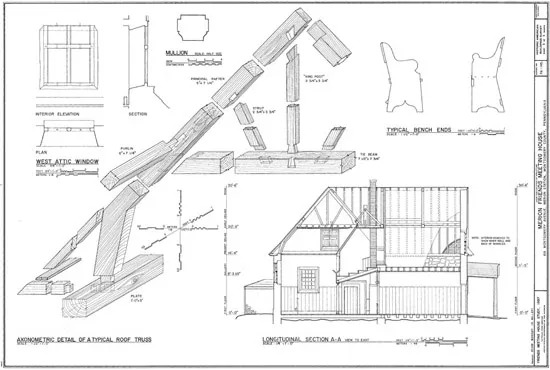
Figure 1.3 Building section and axonometric of a typical roof truss
Source: Historic American Building Survey, c. 1997
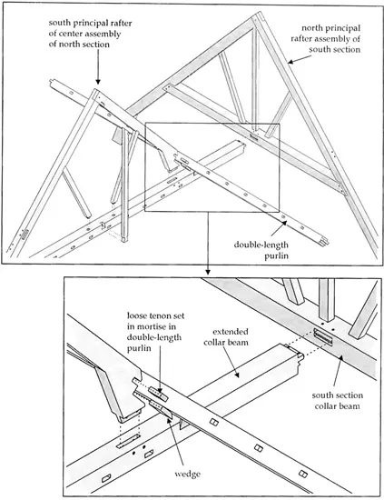
Figure 1.4 Center north cruck frame—south end original support condition
Source: David Mark Facenda, “Merion Friends Meetinghouse: Documentation and Site Analysis,” Thesis for Master of Science in Historic Preservation, University of Pennsylvania, 2002, p. 114
timber. Perhaps this was to avoid breaking an English naval ordinance dated April 22, 1616:
Crooks, Knees, and Compass timber … will be of singular Use for the Navy, whereof principal Care is to be had, in order to the Kingdom’s Safety: It is therefore Ordered and Ordained, by the Lords and Commons in Parliament assembled, That the Crooks, Knees, and Compass Timber, arising from any Trees felled for any of the said Services by Order from the Committee of His Majesty’s Revenue, be reserved to the Use of the Navy, and not disposed of to any other Use.6
Compression and shear forces in a curved timber cause it to bend. If the grain does not follow the curve, then tension stresses will develop across the grain (see Figure 1.3). Factors of safety built into modern codes allow for some nonparallel grain at knots but not across the entire cross section, which woud result in a significant strength reduction.
1.4 Survey and Assessment
John Milner Architects Inc., of Chadds Ford, PA (Daniel Campbell, AIA), retained Suzanne Pentz, the director of historic preservation with Keast & Hood engineers, to assess the building structure following an observation made by a roofer regarding the north wall curvature. The roofer asked if they were to follow the curvature of the supporting wall and the roof edge or to lay the shingles in parallel i.e. straight lines.
During the structural investigation and assessment, Unkefer Brothers Construction Company helped by removing wall finishes where observations were required (i.e., probes).
We discovered that the base of several cruck frames and sill plates that were coincident with the roof valleys had decayed. The north wall was leaning—out of plumb by about one-third of its thickness. Other discoveries included ineffective framing modifications made in the 1800s that will be further discussed, loose king posts, plus rot and termite damage within the crawl space. To quantify the amount of decay at frame bases and wall plates, the assessment included resistance drilling, which allows the investigator to look for decay within the timber.
1.5 Analysis
The north wall displacement was sufficient evidence that the cruck frame supports were yielding, caused by an outward thrust. The plumbness and bowing measurements of the north wall and computer modeling of the entire structure confirmed our assumptions that the structure was in trouble.
Resistance drilling is based on the principle that biological decay of wood is consistently accompanied by reduction in density and therefore in resistance to mechanical penetration. Although the technique itself has been known for decades, it has been recently facilitated by the introduction of the ‘Resistograph’, a proprietary instrument made by Instrument Mechanik Labor (IML) of Wiesloch, Germany. 7
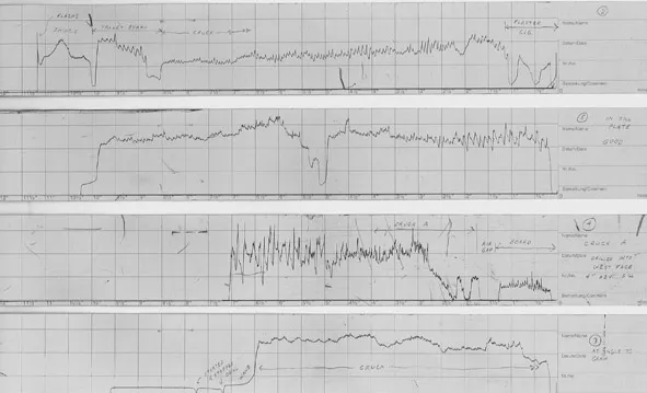
Figure 1.5 Resistograph drill logs. High points are where material is dense; low points indicate decay or voids
Source: Image courtesy Keast & Hood
The computer models also confirmed that support assumptions were dramatically influencing the results. We first modeled a typical frame using a 2-D approach, with one support pinned and the other on a roller, but this predicted incipient failure. We knew the walls were not entirely rigid (fixed), and so we iterated a more detailed 3-D computer model of the entire structure (frames and purlins), assuming varying degrees of lateral stiffness of the walls, until the displacements agreed with field measurements. The predicted lateral thrust exceeded the wall’s resistance, and therefore another...
Table of contents
- Cover
- Title
- Copyright
- Dedication
- Contents
- List of Contributors
- Acknowledgments
- Introduction
- 1 Merion Friends Meetinghouse
- 2 Timber Fundamentals
- 3 Timber Tension
- 4 Timber Bending
- 5 Timber Shear
- 6 Timber Compression
- 7 Timber Trusses
- 8 Timber Lateral Design
- 9 Timber Connections
- Appendix 1 Section Properties
- Appendix 2 Timber Reference Design Values
- Appendix 3 Connection Reference Design Values
- Appendix 4 Adjustment Factors
- Appendix 5 Simple Design Aids
- Appendix 6 Beam Solutions
- Appendix 7 List of Units
- Appendix 8 List of Symbols
- Appendix 9 Imperial and Metric Conversion Tables
- Glossary
- Bibliography
- Index
Frequently asked questions
Yes, you can cancel anytime from the Subscription tab in your account settings on the Perlego website. Your subscription will stay active until the end of your current billing period. Learn how to cancel your subscription
No, books cannot be downloaded as external files, such as PDFs, for use outside of Perlego. However, you can download books within the Perlego app for offline reading on mobile or tablet. Learn how to download books offline
Perlego offers two plans: Essential and Complete
- Essential is ideal for learners and professionals who enjoy exploring a wide range of subjects. Access the Essential Library with 800,000+ trusted titles and best-sellers across business, personal growth, and the humanities. Includes unlimited reading time and Standard Read Aloud voice.
- Complete: Perfect for advanced learners and researchers needing full, unrestricted access. Unlock 1.5M+ books across hundreds of subjects, including academic and specialized titles. The Complete Plan also includes advanced features like Premium Read Aloud and Research Assistant.
We are an online textbook subscription service, where you can get access to an entire online library for less than the price of a single book per month. With over 1.5 million books across 990+ topics, we’ve got you covered! Learn about our mission
Look out for the read-aloud symbol on your next book to see if you can listen to it. The read-aloud tool reads text aloud for you, highlighting the text as it is being read. You can pause it, speed it up and slow it down. Learn more about Read Aloud
Yes! You can use the Perlego app on both iOS and Android devices to read anytime, anywhere — even offline. Perfect for commutes or when you’re on the go.
Please note we cannot support devices running on iOS 13 and Android 7 or earlier. Learn more about using the app
Please note we cannot support devices running on iOS 13 and Android 7 or earlier. Learn more about using the app
Yes, you can access Timber Design by Paul W. McMullin, Jonathan S. Price, Paul W. McMullin,Jonathan S. Price in PDF and/or ePUB format, as well as other popular books in Architettura & Architettura generale. We have over 1.5 million books available in our catalogue for you to explore.