![]()
Engines
Worksheet 1: Vehicle inspections
Procedure
General visual inspection – listen for abnormal noises.
Check brake operation and pad/disc condition – record thickness.
Torque wheel nuts – include torque figures and calibration date of torque wrench.
Additional items – see manufacturer’s schedule depending upon type of inspection – pre- and post-work, PDI, PPI, pre-MOT, VHC or post-repair.
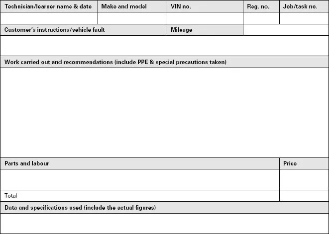
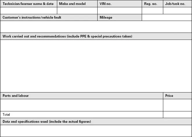
Job card
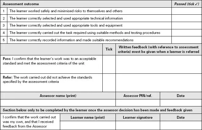
Assessor report
Worksheet 2: Carry out exhaust gas analysis using an exhaust gas analyser
Procedure
Set up the exhaust gas analyser in accordance with the manufacturer’s instructions. Observe all setting conditions – clean air, running time, basic checks for contamination and filter changes.
Run the engine up to normal operating temperature and drive to analyser test area. Insert the exhaust gas probe into the exhaust tail pipe or extraction system probe adapter. Ensure that the probe is inserted to the recommended depth (about 300 mm or 12 inches).
Run the engine at idle and observe and record the readings for gases on the analyser screen.
Run the engine at about 2500 rpm and observe and record the readings for gases on the analyser screen.
Compare the readings with the idle readings and with statutory requirements or manufacturer’s data.
For statutory test certification procedures using an approved gas analyser, follow the on-screen prompt sequence for entering the vehicle data and for connecting the exhaust gas probe and the engine speed tachometer, and in some cases measuring the engine temperature.
Continue to follow the prompt sequence to carry out the test. The result may be given as a pass or fail or as a set of gas percentage (%) values and lambda value for comparison with statutory regulations (different sets of values are used for different years of manufacture).
Job card
Assessor report
Worksheet 3: Remove and replace electronic distributor – strip and reassemble
Procedure
Disconnect battery ground lead. Turn engine to align timing/TDC marks. Remove distributor cap.
Note position of the rotor to the distributor body and of the body to the engine. Compare with manufacturer’s data. Disconnect multiplug to amplifier unit. Disconnect vacuum hose where fitted. Undo and remove, if necessary, distributor clamp bolts – pull out distributor. Inspect drive gear. Undo vacuum unit securing screws and connection to distributor base plate (circlip or hook). Pull out vacuum unit feeding base plate linkage through hole.
Follow manufacturer’s instructions for the removal and replacement of the pulse generator. Remove base plate to access centrifugal advance weights and springs. Remove, inspect and replace as necessary. Lubricate all parts and reassemble in reverse order with new springs if required.
Reassemble pulse generator, check, and adjust air gaps with non-ferrous feeler/gap gauge if appropriate (depe...